


Content last revised on July 3, 2026
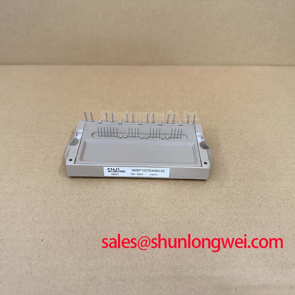
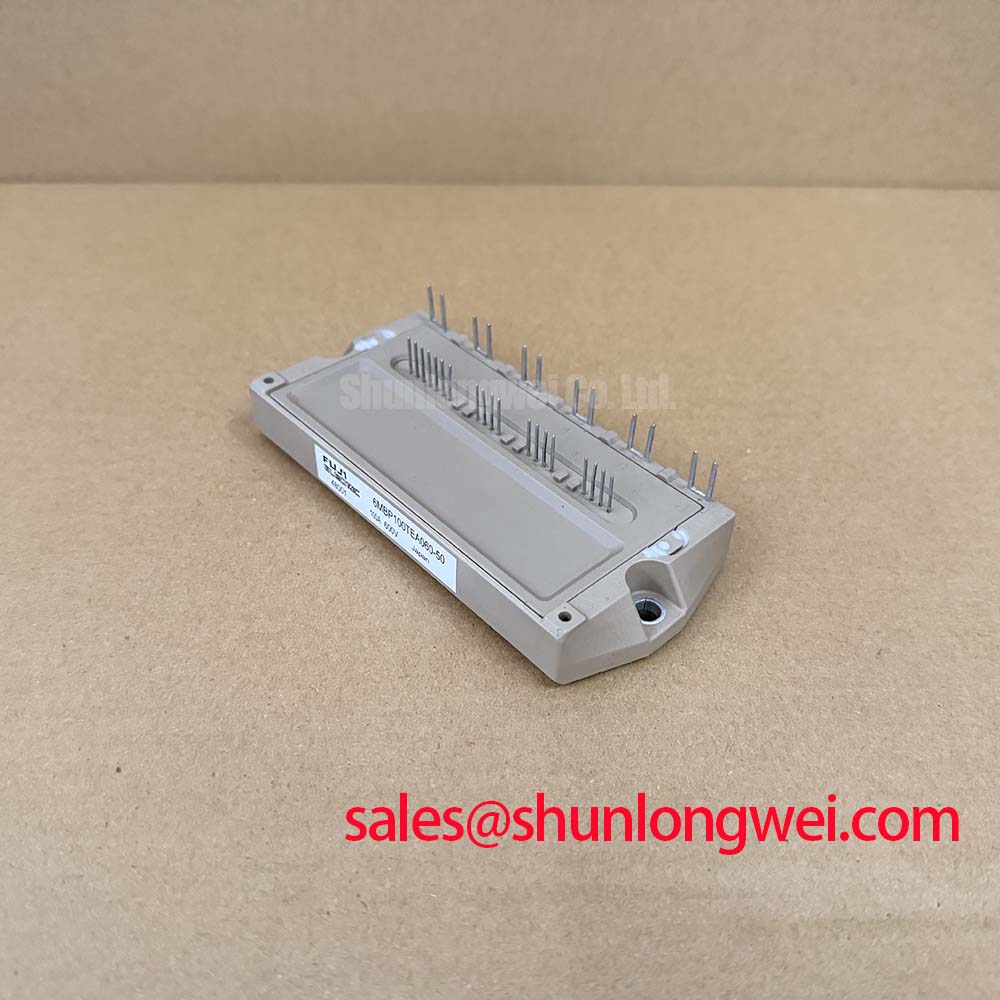
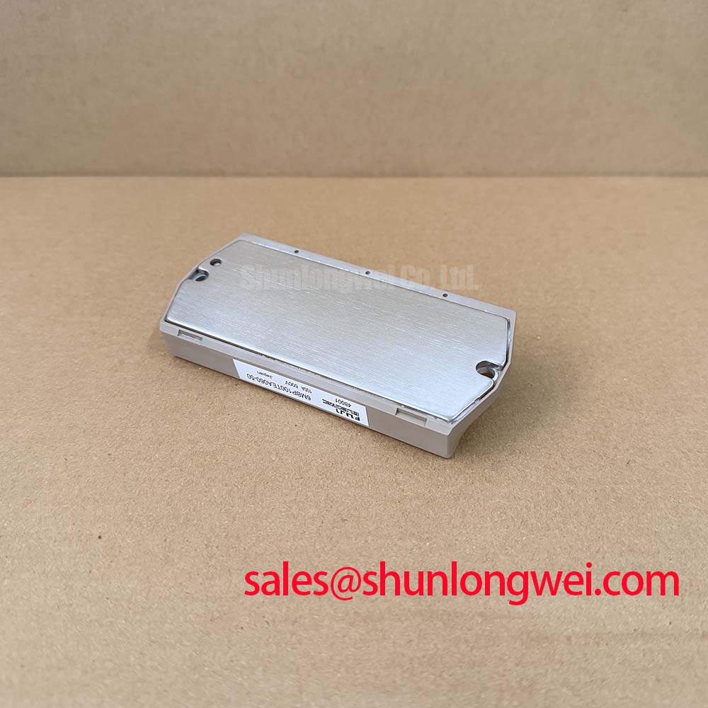
Fuji Electric 6MBP100TEA060-50: 600V 100A Econo IPM for Precision Motor Control
This low-loss, 6-in-one IGBT Intelligent Power Module (IPM) is engineered to simplify layout design while maximizing switching efficiency in industrial AC drive systems.
Specifications: 600V | 100A | Rth(j-c) 0.36 °C/W.
Key Benefits: Real-time temperature protection; Reduced external component count.
To prevent failures, does the integrated junction temperature detection eliminate the need for external thermistors? By integrating direct silicon-level junction temperature sensing on each IGBT chip, this module provides real-time thermal protection, eliminating external NTC placement lag. For 400V AC motor drives prioritizing switching efficiency and high-speed protection, the 6MBP100TEA060-50 is the optimal choice.
Application Scenarios & Value
Achieving High-Efficiency Motor Drives with Low Conduction and Switching Losses
Engineers often face the daunting task of designing compact, high-efficiency motor controllers that can withstand harsh operating environments without sacrificing thermal safety. The 6MBP100TEA060-50 simplifies this challenge by combining a six-pack IGBT topology with integrated drive and protection circuitry in a single package.
In modern Variable Frequency Drive (VFD) applications, managing switching transients while keeping the footprint minimal is a common bottleneck. This module provides a robust solution for driving AC motors up to 100A under a maximum 600V collector-emitter rating, allowing designers to bypass the complex layout challenges of discrete power stages.
By optimizing the internal chip layout to match the thermal demands of heavy-duty industrial systems, it reduces conduction losses during peak loading. For systems that require higher current handling or alternative packaging configurations, the related 6MBP100RTA060 offers an alternative mechanical design.
The integrated layout minimizes parasitic loop inductances, which directly prevents overvoltage spikes during rapid turn-off transitions. This level of integration is essential for achieving compliance with EMC standards and minimizing system-level thermal footprints, in line with the standards defined by Fuji Electric.
Technical & Design Deep Dive
Integrating Gate Driver and Silicon-Level Protection for Minimal Parasitic Loop Inductance
A key technical feature of the 6MBP100TEA060-50 is its integrated pre-driver stage, which eliminates the need for external gate resistors and complex driver circuitry.
An IPM's integrated pre-driver is like a localized signal amplifier on a high-fidelity speaker; by placing it directly next to the IGBT gate, it eliminates the long cable run that would introduce noise and signal degradation, ensuring crisp, fast switching with minimal distortion. This close coupling is essential for mitigating parasitic turn-on events caused by high dv/dt transients.
Furthermore, the module integrates a dedicated gate drive supply under-voltage lockout (UVLO) mechanism. When the control supply voltage falls below 12.5V, the internal protection circuit automatically disables the IGBTs, preventing them from operating in the high-loss linear region, which could lead to catastrophic thermal runaway.
To ensure safe operation, a minimum dead-time insertion of 1.0 µs is recommended between the top and bottom arm input signals to prevent shoot-through currents across the DC bus. This protection scheme makes ipm vs discrete igbt selection a straightforward choice for engineering teams seeking to reduce design-in time and maximize field reliability.
The module also features direct chip-level over-temperature protection. When the silicon junction temperature exceeds 150°C, the IPM triggers a fault alarm.
Think of the thermal hysteresis (TjH = 20°C) as a thermostat with a cooling buffer; it prevents the system from rapidly oscillating on and off near the trip point, much like a furnace that waits for the house to cool slightly before kicking back on, protecting the system from thermal fatigue.
For reference, what is the primary benefit of direct temperature sensing? It eliminates measurement lag associated with external thermistors. What voltage triggers the UVLO function? The protection activates when the pre-driver supply falls below 12.5V.
Key Parameter Overview
Specifications and Engineering Value for Optimized Thermal Design
| Parameter | Typical Value / Rating | Engineering Value |
|---|---|---|
| Collector-Emitter Voltage (VCES) | 600V | Defines the maximum blocking voltage for 200V-400V AC line systems. |
| Continuous Collector Current (IC) | 100A (at Tc=25°C) | Enables direct control of high-power industrial motors under continuous load. |
| Isolation Voltage (Viso) | AC 2500V (1 minute) | Ensures user and low-voltage control circuit safety by separating power baseplate. |
| Under-Voltage Lockout (VUV) | 11.0V to 12.5V | Safeguards the gate drive by halting operation before low gate voltage causes linear-mode destruction. |
| Thermal Resistance (Rth(j-c)) | 0.36 °C/W (IGBT) / 0.665 °C/W (Diode) | Enables efficient thermal transfer to the heatsink, lowering operational junction temperatures. |
Download the 6MBP100TEA060-50 datasheet for detailed specifications and performance curves.
Frequently Asked Questions
Addressing Common Engineering Inquiries for Practical System Integration
How does the integrated junction temperature detection on the 6MBP100TEA060-50 compare to external thermistors?
By integrating direct silicon-level junction temperature sensing on each IGBT chip, this module provides real-time thermal protection, eliminating external NTC placement lag.
What is the engineering significance of the Rth(j-c) value of 0.36 °C/W?
This low junction-to-case thermal resistance allows the module to efficiently transfer dissipated heat to the heatsink. It reduces the size of the required heatsink, boosting overall power density.
Why is the 1.0 µs dead-time recommendation critical for this IPM?
The 1.0 µs dead-time prevents shoot-through currents across the DC bus, ensuring that one arm of the inverter phase completely turns off before the opposite arm turns on.
Does the 6MBP100TEA060-50 feature a built-in brake chopper circuit?
Unlike the 7MBP series which typically integrates a brake stage, the 6MBP100TEA060-50 is a dedicated six-pack (6-in-1) inverter topology without an integrated brake chopper, allowing custom braking solutions.
What are the recommended gate drive supply voltage limits for stable operation?
The recommended pre-driver supply voltage is 13.5V to 16.5V (typically 15V). Operating below 11.0V will trigger the under-voltage protection to protect the module.
From an integration perspective, utilizing this IPM minimizes the PCB real estate dedicated to driver routing. Decoupling capacitors must be placed as close to the pre-driver supply pins as possible, and signal tracks should be routed carefully to maintain noise immunity. Designers should consult the official IGBT thermal management guidelines and preventing IGBT failure modes to ensure adequate safety margins under worst-case loading.