Content last revised on October 20, 2026
Initial Inspection
- With the drive isolated and its DC link confirmed discharged, inspect the module terminals and surrounding board for discoloration, cracked solder joints, contamination, or mechanical strain.
- Compare the installed part marking with 6MBP1RA120 and verify the specified voltage and current ratings against the drive documentation.
- Check that the heat sink is clean, the mounting surfaces are seated evenly, and the cooling path is unobstructed.
- Inspect gate-drive and motor connections for loose terminations, damaged insulation, or routing changes made during previous service.
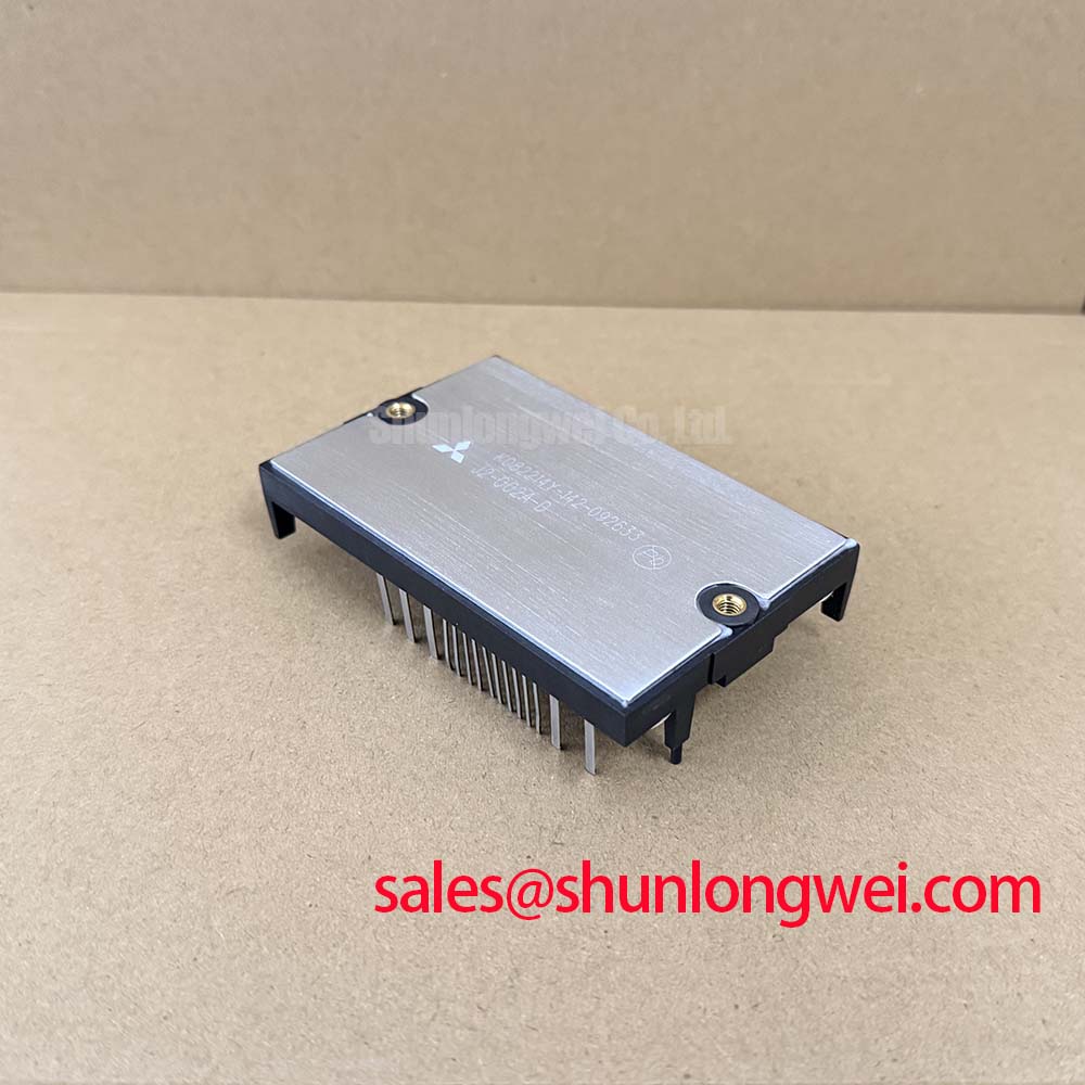
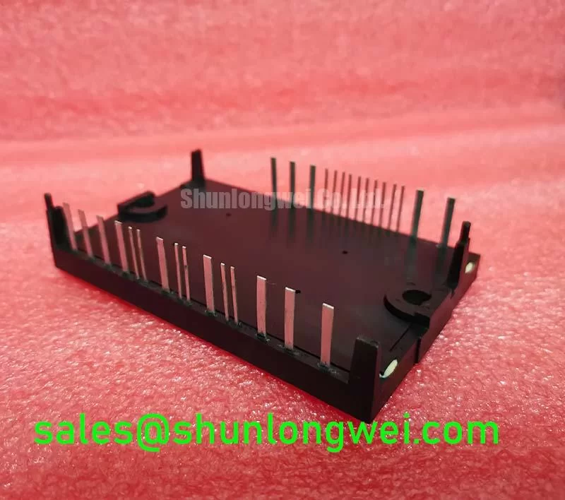
6MBP1RA120 is a Fuji Electric IPM Module identified with a 1200.0 V rated voltage, a 1.0 A rated current, and a Fuji Power Module package. These are the supplied product specifications; they do not by themselves establish suitability for a particular drive position, switching frequency, braking duty, or cooling arrangement. For repair evaluation, compare the complete part number and the original equipment requirements before installation.
| Product attribute | Specification |
|---|---|
| Manufacturer | Fuji Electric |
| Model | 6MBP1RA120 |
| Product category | IPM Module |
| Rated voltage | 1200.0 V |
| Rated current | 1.0 A |
| Package | Fuji Power Module |
In a multi-axis CNC or robotics servo cabinet, this part may be considered during repair only where the existing circuit position and system documentation match its specified role. A module’s name or package family is not enough to infer terminal assignment, control logic, protection behavior, or interchangeability. Keep the original wiring records and board references available when tracing the power stage. The linked 6MBP75NA060 is another device that can be reviewed as a separate candidate; do not treat it as a drop-in replacement without checking the relevant electrical, mechanical, and control requirements.
Preventing Spurious Faults: Long Motor Lead Reflected Wave Voltage Guidelines for 6MBP1RA120
When a servo drive reports overvoltage or exhibits intermittent power-stage faults after a motor cable change, first compare the cable route, motor connection, and drive output waveform with the known-good installation. A long motor lead can behave as a transmission path: impedance mismatch at the motor end may reflect switching edges back toward the drive and increase terminal voltage stress. The magnitude depends on the drive output, cable characteristics, motor termination, and switching conditions; a fixed multiplier should not be assumed for every installation.
Design Consideration: use an oscilloscope and a suitably rated differential probe to examine the voltage at the drive output and, where practical, at the motor terminals during representative operation. Follow the instrument manufacturer’s safety limits and measurement procedures. Compare the observed waveform with the drive and motor documentation, paying attention to overshoot, ringing, and changes with cable length or routing. Do not attach a conventional grounded probe to a switching node unless the measurement setup is specifically designed for it.
If ringing is present, review the motor cable type and termination, output filter compatibility, and the drive manufacturer’s guidance for cable length. A dv/dt filter or output choke may be considered when the drive and motor documentation support that solution. Filter selection is system-dependent: account for the drive’s switching behavior, motor insulation requirements, cable capacitance, and the filter’s thermal and electrical ratings. Verify the outcome through measurement under representative load rather than relying on a general cable-length rule.
Keep motor conductors separated from low-level encoder and command wiring where cabinet layout allows, and avoid routing changes that create larger switching-current loops. Inspect cable shields and bonding according to the equipment’s installation instructions. These practices are general engineering considerations, not additional ratings for the module. For converter terminology and equipment context, consult the IEC 60146 semiconductor converters standard.
For a servo system with a separate front-end or auxiliary power stage, document the topology before attributing a fault to one module. The 2MBI300VW-120D-51 is a distinct power module that may be relevant when reviewing related equipment components; its presence does not establish a direct electrical relationship or a suitable replacement for this part.
6MBP1RA120 Thermal-Electrical Optimization: Thermal Cycling Margins of Internal Braking Practical Tuning
During deceleration, a servo motor can return energy to the DC link, so the drive’s braking path must be evaluated as part of the complete system. Establish from the circuit diagram whether braking is handled by an internal switching element, an external braking unit, or another arrangement. Do not infer that the 6MBP1RA120 includes a braking function from the model designation or the supplied voltage and current ratings alone.
Engineering Recommendation: check the drive manual for the braking circuit’s operating thresholds, allowable resistor configuration, and thermal limits. The resistor’s energy and power requirements depend on the moving load, inertia, deceleration profile, repetition rate, and available energy-handling path. Commissioning should therefore use the machine’s actual motion profile and the manufacturer’s permitted configuration. A resistor that appears suitable by nominal resistance alone may still be unsuitable for repeated braking duty.
When a braking event coincides with a DC-link rise or drive trip, record the event timing and compare it with the axis command, bus-voltage indication, and braking-control activity. Review whether deceleration settings or machine load have changed since the last known-good run. This narrows the investigation without assuming that a single symptom identifies a failed module.
Freewheeling diode recovery and switching transitions can contribute to voltage ringing and conducted or radiated interference in a power stage. The relevant behavior depends on the circuit and the selected device characteristics. Keep commutation paths compact, avoid unnecessary loop area, and use snubber components only where the circuit design and measured switching behavior justify them. Any mitigation should be checked for its effect on switching loss, component temperature, and the drive’s emissions as a complete assembly; the module itself should not be described as independently certified for system EMC compliance.
The semiconductor physics behind switching behavior is discussed in the reference on drift velocity and carrier mobility in silicon and wide-bandgap semiconductors. It provides general background, not device-specific switching data for this model.
Field Diagnostics & Commissioning: Preventing Ceramic Substrate Rupture during 6MBP1RA120 Topologies
Uneven contact between a power module and its heat sink can impair heat transfer and place mechanical stress on the assembly. Before mounting, inspect both mating surfaces for debris, burrs, corrosion, or visible damage, and confirm that the heat sink has not been distorted. Use the mounting sequence and fastener requirements specified by the equipment or module documentation; do not substitute an assumed torque value or tightening pattern for the applicable instructions.
Apply thermal interface material in the manner specified for the selected material and assembly. A uniform, controlled layer is the objective, but a particular thickness cannot be assigned to this module without supporting documentation. Tighten fasteners gradually and evenly using the prescribed method, avoiding local force that could bend the baseplate or load the module unevenly. If the module does not sit flat, stop and identify the mechanical cause rather than pulling it into position with the fasteners.
After reassembly, check that the heat sink is clear of dust and that airflow reaches the module as intended. During service inspections, compare operating temperatures and terminal condition with the equipment’s established baseline. Look for changes in contact temperature, fan performance, contamination, or signs of thermal-interface deterioration. Maintenance Note: monitor contact temperature trends and verify that the cabinet airflow path remains clear during scheduled service.
For broader inverter topology context, see Peak Efficiency in Solar and Energy Storage; topology guidance should be applied only where it matches the actual equipment circuit. In servo cabinets evaluated for CNC axes or robotic motion systems, confirm that mounting, cooling, wiring, and control interfaces match the machine documentation before returning the assembly to operation.