
Content last revised on September 17, 2026
Assembly Integrity & Layout Architecture: Evaluating High-Altitude Cosmic Ray Induced SEB Risk for 6MBP400RTM060
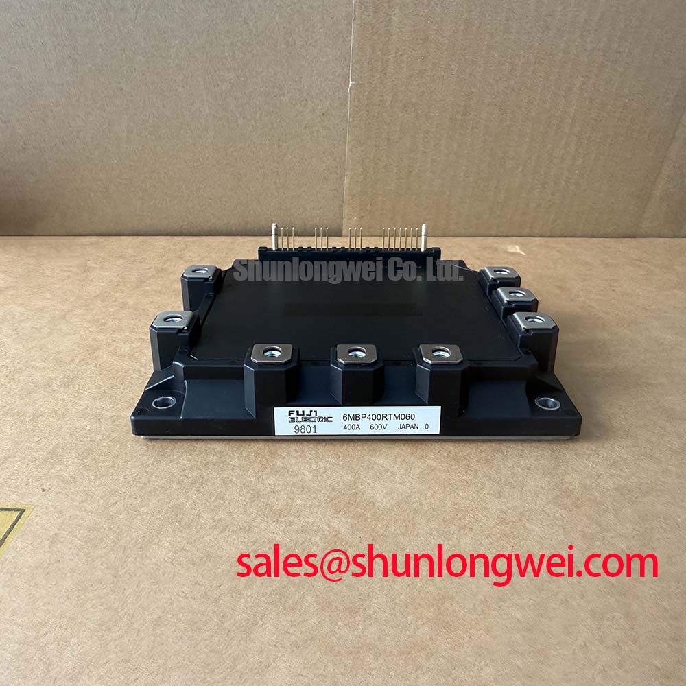
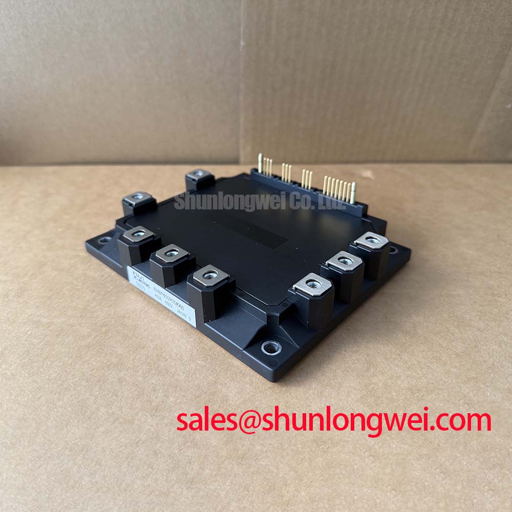
With the inverter isolated, discharged, and removed from its equipment, begin incoming inspection by matching every power and control terminal to the original equipment documentation, then record cold-state readings before applying any supply. The Fuji Electric 6MBP400RTM060 is an IPM module officially rated at VCES = 600 V and IC = 400 A at TC = 25 degrees C. Its stated 2500 V AC isolation voltage for 1 minute separates the power terminal domain from the control interface under the specified test condition, while integrated over-current, over-temperature, and under-voltage protections are part of the module feature set.
For repair assessment, treat the 600 V collector-emitter rating as an Official Datasheet Specification and verify it against the actual DC bus and measured switching overshoot. A utility-scale 1500 V solar inverter is not a direct application for a 600 V power stage. Engineers evaluating this module within that equipment class should restrict the assessment to appropriately rated lower-voltage auxiliary subsystems, such as cooling, pumping, cabinet ventilation, or other motor-drive assemblies, after confirming the original circuit voltage and terminal arrangement.
Bench Tip: Establish cold-state readings with the same meter, lead polarity, and isolated terminal condition each time, because an unverified residual charge or connected control board can invalidate a diode-mode comparison.
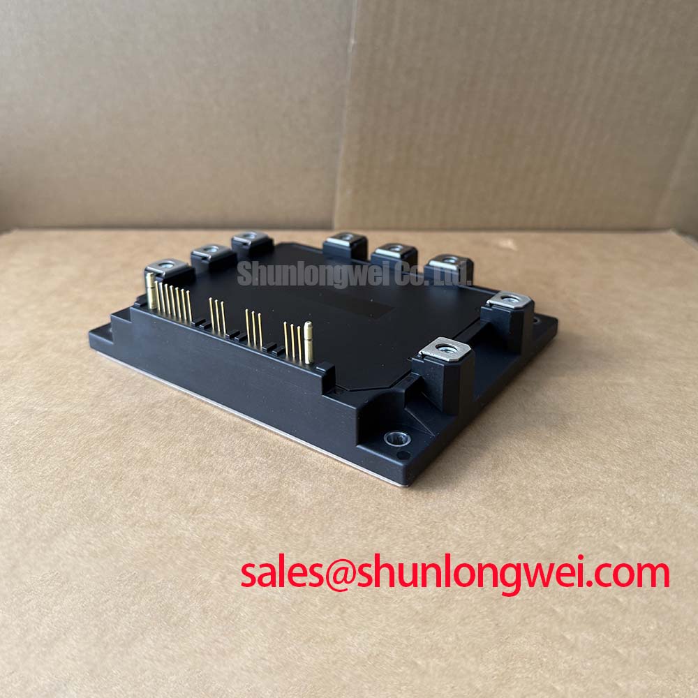
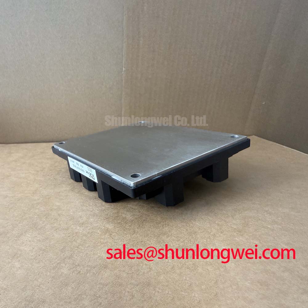
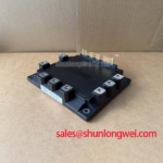
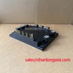
Start mechanical assessment with the module baseplate, power-terminal interfaces, and control connector area. Look for uneven contact marks, cracked plastic around terminal locations, heat discoloration, distorted mounting surfaces, and evidence that the module was clamped against a contaminated heatsink. These observations do not establish an electrical fault on their own, but they identify locations that merit closer examination before a replacement assembly is energized.
The 6MBP400RTM060 has an Official Datasheet Specification of 600 V VCES. That rating is the primary electrical boundary for DC-link evaluation. During turn-off, unavoidable circuit inductance can add a voltage excursion to the DC bus, so the relevant measurement is the peak collector-emitter stress observed in the finished inverter, not the nominal bus value alone. A Design Consideration is to keep the commutation path physically compact and to verify peak voltage at the device connection during representative switching tests.
High-altitude operation above 2000 m can change the environmental conditions considered by a system designer, including insulation coordination, cooling performance, and exposure to terrestrial neutron flux. No device-specific SEB rate, FIT figure, altitude derating curve, or cosmic-ray qualification result is provided in the supplied official specifications for this model. It would therefore be inaccurate to assign a failure probability or prescribe a DC-bus derating percentage for the module. For equipment installed at altitude, the Engineering Recommendation is to use the original inverter qualification requirements, measured voltage waveforms, thermal measurements, and applicable system safety documentation to determine whether the assembly remains within its required operating margin.
On a repair bench, distinguish a protection response from a failed power path by first checking wiring, connector seating, drive-power rails, and fault-memory information supplied by the host controller. A persistent fault may originate in the external current-sensing circuit, cooling interlock, command interface, or the IPM itself. With power removed, compare the suspected assembly against a known-good signal path where available. Do not infer cosmic-ray damage from one static resistance measurement.
DC-link capacitors also shape the switching environment seen by the power stage. Their ripple-current capability, connection resistance, and placement affect bus stability and transient behavior. For background on capacitor construction and use in DC-link service, see Film Capacitors in High Ripple Current DC-Link Applications. This is general technical context rather than a specification for any capacitor or for the 6MBP400RTM060.
When a repair bill of materials lists a 6MBI100L-060, it should be treated as a separate device for document-based comparison, not as an automatic substitute. Terminal configuration, current capability, control arrangement, protection functions, mechanical fit, and system qualification must be verified against the original assembly before any replacement decision is made.
Transient Dynamics & Electrical Design: Active Miller Clamp Evaluation for 6MBP400RTM060
Before evaluating gate-drive behavior, confirm the exact control-pin identity from the original module documentation and the host equipment schematic. An IPM module combines power switching elements with internal control and protection functions, so its input interface must not be assumed to behave like the gate of a discrete IGBT. The Official Datasheet Specification provided for this model identifies integrated over-current, over-temperature, and under-voltage protections, but it does not specify an active Miller clamp, a negative gate-bias range, gate resistance, switching frequency, or gate-charge value.
An active Miller clamp is a Design Consideration at the driver level when high switching-node dv/dt could couple through capacitances and disturb an off-state control input. Whether such a function is relevant to the 6MBP400RTM060 depends on the installed controller, interface circuit, and module documentation. Designers should inspect the turn-off command waveform and the device control reference under real load conditions, then verify that any clamp arrangement is compatible with the module input limits and fault logic.
Negative gate bias is often discussed in discrete IGBT driver design, but no negative-bias operating instruction is included in the supplied official data for this IPM. It must not be imposed as a default setting. The system integrator should verify the required input-drive levels from the original Fuji Electric documentation and the equipment driver schematic. Where unwanted turn-on is suspected, an oscilloscope comparison of command signals, power-stage switching nodes, and local driver reference can help identify common-mode movement, connector faults, or a layout-related issue without assigning a single cause prematurely.
Switching-frequency and cooling decisions are system-determined. The 400 A at TC = 25 degrees C value is an Official Datasheet Specification, not a guarantee that the same current is available at every heatsink temperature, airflow condition, modulation method, or switching frequency. Evaluate current demand alongside measured case temperature, duty cycle, ambient conditions, and the converter waveform. If a cabinet cooling path has been altered, inspect fan operation, filter blockage, heatsink contact, and airflow direction before attributing a thermal alarm to the module.
A replacement IPM must also be checked within the wider converter topology. An item such as the 6MBI15L-060 can be reviewed as a separate complementary power-semiconductor reference in related rectifier or auxiliary circuits, but its use, location, and compatibility are determined by the original equipment circuit rather than by a shared voltage-class label.
6MBP400RTM060 Circuit Protection & Reliability: Evaluating Thermal Capacitance Versus Heatsink Response
A useful first check after a thermal or over-current trip is to inspect the physical heat-transfer path rather than relying on a static electrical test alone. Remove power, allow the assembly to cool, and examine the heatsink mounting face for debris, corrosion, uneven thermal compound coverage, or a mounting pattern that has been tightened unevenly. The module protection features can reduce exposure during abnormal operation, but they do not remove the need for a sound thermal interface or a correctly functioning cooling system.
Field Alert: Disconnect and discharge the DC link before touching module terminals or removing control connectors, because stored energy and unverified interconnections can create a hazardous test condition.
Junction-to-case transient thermal behavior is normally assessed from manufacturer-provided transient thermal impedance information and a defined power-loss waveform. The supplied official parameters do not include a thermal impedance curve, junction temperature limit, thermal resistance, case outline, mounting torque, or a multi-RC thermal model. Consequently, a calculated peak junction temperature would not be defensible from the available data. Do not create a thermal-capacitance calculation using assumed values and label it as a property of this module.
An Engineering Recommendation is to use the original module datasheet and host inverter design record to obtain the applicable thermal model, then correlate it with measured case temperature and the actual pulse profile. When a repeated fault appears only under load, capture the timing of the protection signal, output current, cooling status, and DC-bus behavior. That evidence can separate a genuine thermal loading concern from a blocked airflow path, intermittent temperature-sensor connection, abnormal load, or protection-control issue.
Protection evaluation should remain tied to the installed system. The 6MBP400RTM060 integrates OC, OT, and UV functions according to the supplied official information, yet the trigger thresholds, fault timing, reset behavior, and host-controller reaction must be confirmed from original documentation. Avoid defeating a trip input or repeatedly resetting an alarm during diagnosis. A protective event is measurement evidence that should be preserved and investigated.
For broader comparison of high-power semiconductor module practices and package families, Powerex High Power Semiconductor Modules provides industry reference material. It does not establish equivalent ratings, thermal behavior, or pin compatibility for the Fuji Electric 6MBP400RTM060.
Preventing Spurious Faults: Isolated DC-DC Power Supply Evaluation for 6MBP400RTM060
Spurious protection reports often require inspection of the control-power path before the power module is condemned. Check the isolated supply output at the driver connection while the system transitions through startup, enable, load change, and fault reset. Observe whether supply interruption, connector movement, noise coupling, or an external interlock coincides with the event. The module includes under-voltage protection as an Official Datasheet Specification feature, so its control supply behavior is relevant to fault diagnosis even when the power terminals pass a cold-state check.
The module isolation rating is 2500 V AC for 1 minute, an Official Datasheet Specification for galvanic isolation between the applicable power and control domains under that test condition. It is not evidence that an external isolated DC-DC converter provides reinforced isolation, a particular working-voltage rating, a specified common-mode transient immunity value, or compliance with an equipment-level standard. Those properties belong to the selected power supply, PCB layout, insulation system, and final equipment assessment.
For a controller that shares measurement, communication, and gate-command references across a noisy power stage, a Design Consideration is to preserve the intended isolation barriers and minimize coupling paths created by routing, shields, connectors, and ground returns. The practical verification is waveform-based: compare the isolated supply output and control reference against the switching event, using a measurement method appropriate for the voltage environment. A correlation may indicate common-mode interference, but confirmation requires comparison with the known-good circuit behavior and the original control design.
In a utility-scale solar inverter cabinet, the 6MBP400RTM060 should not be represented as a module for direct connection to a 1500 V DC bus because its official VCES rating is 600 V. For lower-voltage auxiliary drive assemblies, confirm the subsystem bus voltage, motor demand, control interface, cooling arrangement, and protection wiring individually. Engineers needing general switching-loss and industrial-drive context can consult Unlocking Efficiency in Industrial Drives as background reference, while retaining the original Fuji Electric documentation as the authority for this specific module.