

Content last revised on September 19, 2026
6MBP75RSA120-03 Operational Boundaries: Evaluating Motor Cable Impedance Mismatch
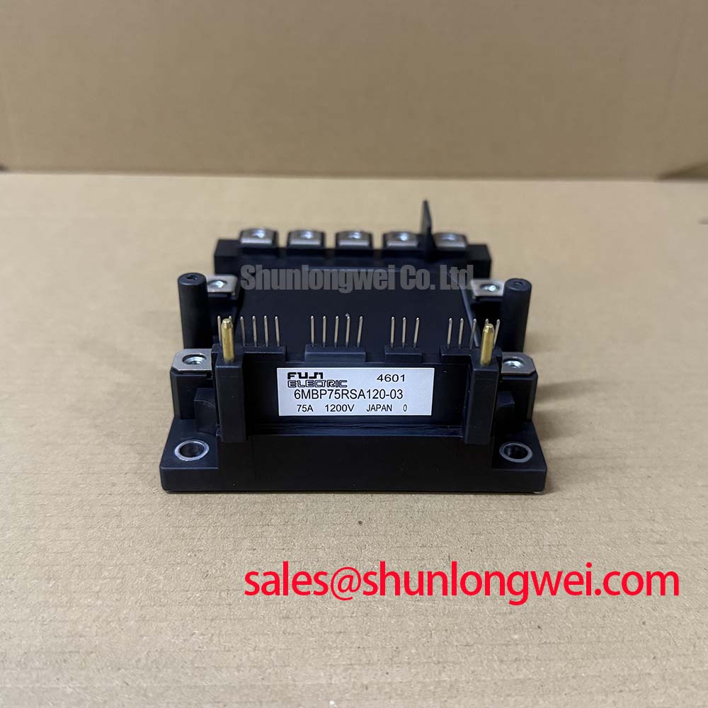
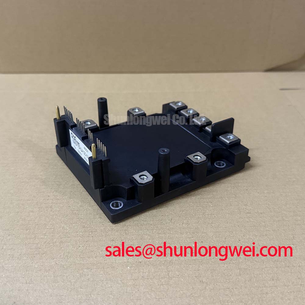
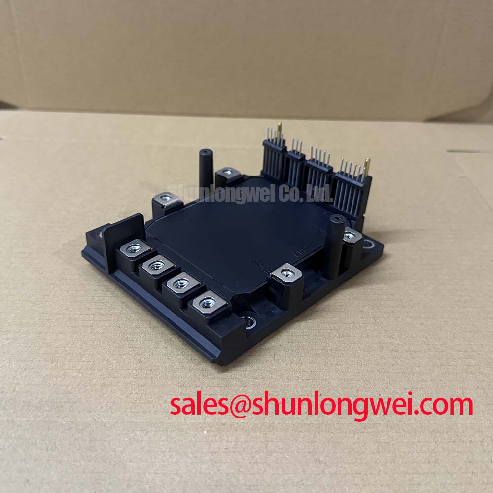
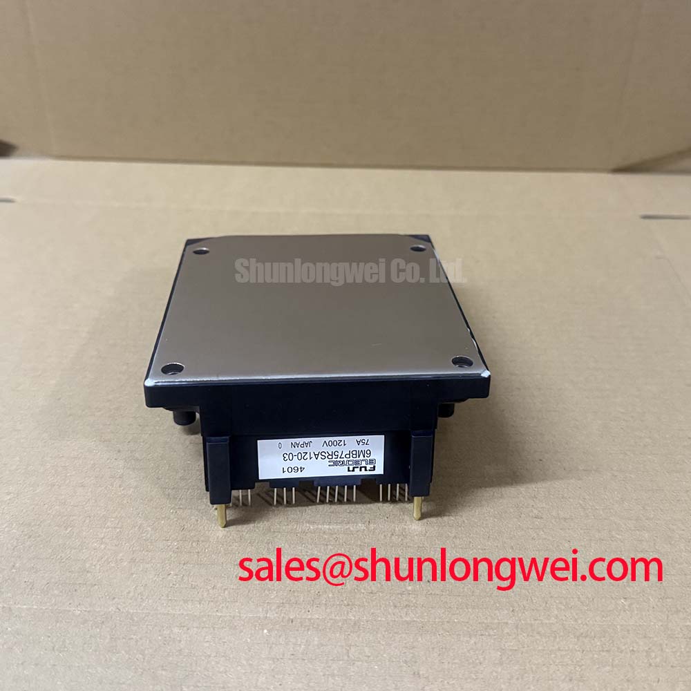
Before energizing a replacement inverter, verify the 6MBP75RSA120-03 nameplate, inspect the power terminals for deformation, and measure the unpowered phase paths against a known-good assembly. The Fuji Electric IPM is specified at VCES = 1200 V and IC = 75 A at TC = 25°C. Its typical collector-emitter saturation voltage is VCE(sat) = 2.2 V at TJ = 125°C and IC = 75 A. These are official product specifications; actual operating limits still depend on switching frequency, thermal impedance, current waveform, cooling hardware, and the complete inverter design.
Long motor cables should be treated as part of the switching network rather than as ideal conductors. Their distributed inductance and capacitance can reflect fast voltage edges back toward the inverter terminals. Under some cable and termination conditions, the motor-end voltage can approach approximately twice the DC-link voltage during a reflection event. This is a system-level design consideration, not a guaranteed behavior of every installation, so the actual waveform should be checked at the module output and motor terminals with suitable high-voltage probing.
For a low-voltage traction inverter used in an electric forklift or warehouse vehicle, the evaluation should begin with the actual battery or DC-link voltage, cable length, conductor arrangement, motor input characteristics, and switching pattern. The 1200 V VCES rating provides a defined device boundary, but it does not remove the need to verify repetitive overshoot. Designers should assess peak voltage, ringing frequency, damping, and the effect of regenerative braking before approving the operating envelope.
Output chokes, dv/dt filters, or motor-side filtering may reduce reflected-wave stress when the measured waveform shows excessive ringing. The filter should be selected from the complete motor-drive response rather than from the module rating alone. Excessive filtering can alter current control, increase losses, or affect regeneration, so the system engineer should validate phase current, torque response, thermal performance, and insulation stress during commissioning.
Field troubleshooting is most useful when measurements are taken at several points. Compare the inverter output, the far end of the motor cable, and the DC-link waveform during acceleration, deceleration, and fault recovery. A difference between a clean inverter-side waveform and a heavily ringing motor-side waveform may indicate cable impedance interaction, termination effects, or a filter resonance. It should not be assigned to a single cause without checking probe grounding, measurement bandwidth, cable routing, and the known-good signal path.
The integrated overcurrent, short-circuit, control-supply undervoltage, and overtemperature protections are official functional features listed for this IPM. Their response timing and external control interlock should be verified from the applicable Fuji Electric documentation and the host inverter schematic. Protection circuitry does not replace current sensing, controlled shutdown, precharge management, or safe isolation in the vehicle system.
Assembly Integrity and Layout Architecture: Symmetrical Busbar Geometry
During inspection, trace the commutation loop from the DC-link capacitors through the IPM and back to the capacitors. The physical arrangement should minimize loop area and keep the positive and negative current paths closely coupled. A planar or laminated busbar arrangement can reduce parasitic inductance when its geometry is maintained through the full high-current path. The suitable construction remains system-dependent and should be confirmed by switching measurements.
Turn-off overshoot is governed by the interaction between stray inductance and current-change rate. In engineering analysis, the additional voltage is commonly related to the product of commutation-loop inductance and di/dt, added to the instantaneous DC-link voltage. This relationship explains why a module with an adequate static voltage rating can still experience excessive dynamic stress if the busbar, capacitor connection, or phase output layout is poorly arranged.
Do not infer busbar quality from visual symmetry alone. Check the distance between the DC-link capacitor terminals and the module terminals, inspect overlapping conductors for movement or insulation damage, and confirm that mounting pressure has not distorted the power interface. The snubber or local high-frequency capacitor network should be located according to the inverter manufacturer’s validated layout. Its value and current rating must be selected from measured ringing energy, switching frequency, and thermal results rather than copied as a universal prescription.
When several power modules are operated in parallel, static current sharing is influenced by electrical path resistance, gate-drive matching, thermal coupling, and the temperature behavior of VCE(sat). The positive temperature coefficient commonly associated with IGBT conduction voltage can support static sharing, but it does not guarantee equal dynamic current during turn-on and turn-off. Gate-loop symmetry, identical conductor length, and synchronized drive signals should therefore be checked independently.
The rated current of 75 A at TC = 25°C must not be interpreted as a universal vehicle-output current. Case temperature, duty cycle, switching loss, thermal interface condition, airflow, and overload duration determine the usable current in the finished traction inverter. A current waveform captured at the DC link should be compared with phase current and device temperature during the intended duty cycle.
💡 Pro Tip: Keep the gate-drive return and high-current commutation paths physically controlled, then confirm the remaining voltage overshoot with a properly compensated differential probe during double-pulse or equivalent switching tests.
For a broader comparison of an alternative Fuji Electric power module configuration, engineers may review 6MBI100S-140 as a separate reference device. It should not be treated as a drop-in replacement without checking electrical ratings, terminal arrangement, protection behavior, gate-drive requirements, mechanical fit, and thermal design.
Field Diagnostics and Commissioning: Gate Control and Miller Immunity
Commissioning should start with the gate-emitter waveform at the module pins, not at a distant driver-board test point. Check the signal during normal switching, inhibited switching, undervoltage events, regenerative operation, and the fault response. A gate waveform that appears acceptable at the driver can differ at the module because of common-emitter inductance, connector impedance, return-current coupling, or an incorrectly routed control cable.
High dv/dt at the switching node can capacitively couple into an opposing gate circuit. The resulting transient may produce unintended gate movement and possible cross-conduction. A low-impedance active Miller clamp can help hold the inactive device gate at its intended state, provided the circuit is compatible with the IPM interface and the protection sequence. The need for negative gate bias must be established from the applicable Fuji Electric gate-drive specification and the measured immunity of the complete bridge; a generic negative-voltage value should not be imposed on this model without documentation.
Verify the control-supply undervoltage path before applying the full DC link. Confirm that the driver disables switching when the supply leaves its permitted range, that fault feedback reaches the controller, and that restart behavior is deliberate. The integrated OC, SC, UV, and OT functions should be considered part of a coordinated protection architecture, not as a substitute for external gate interlocking and fault-energy management.
If an apparent shoot-through event occurs, record the gate signals of both devices, the DC-link current, and the switching-node voltage on the same time base. Also inspect the gate resistor population, driver isolation, connector seating, and the return-current route. A distorted gate pulse may result from excessive loop inductance, driver saturation, false fault triggering, or measurement interference. The corrective action should follow the measured signal relationship rather than a single assumed failure mechanism.
In a traction system, motor regeneration can expose gate-drive weaknesses that are not visible during unloaded forward rotation. Test transitions in both current directions and include the battery or DC-link conditions expected during braking. The associated topology and commutation behavior can be compared with the practical discussion of Resonant Topologies in Home Appliances, while recognizing that the forklift traction inverter has different control, load, and protection requirements.
Transient Dynamics and Electrical Design: Thermal Capacitance Under Pulsed Load
A short overload does not raise junction temperature instantaneously to the same value predicted by steady-state thermal resistance. The semiconductor die, case, thermal interface, heatsink, and cooling path store and release heat over different time scales. For this reason, pulsed-current evaluation should use the manufacturer’s transient thermal impedance information where available and should distinguish junction-to-case behavior from case-to-heatsink and heatsink-to-ambient performance.
The specified VCE(sat) of 2.2 V typical at 125°C and 75 A helps estimate conduction loss, but it is not a complete loss model. Switching energy, diode recovery behavior, current direction, gate resistance, DC-link voltage, junction temperature, and modulation strategy also contribute. The freewheel diode’s reverse-recovery softness can influence voltage ringing and EMI, so the phase-node waveform should be recorded together with current and gate voltage rather than evaluated from conduction voltage alone.
For a forklift traction application, evaluate acceleration, steady travel, lifting-related auxiliary demand where applicable, plugging or regenerative braking, and repeated stop-start cycles. The thermal model should use the measured current waveform and switching pattern. Peak junction-temperature margin should then be checked against the official device limits and the validated cooling assembly. A case-temperature sensor by itself may miss short-duration junction excursions.
Thermal inspection should include the contact surface, interface material coverage, heatsink flatness, clamping condition, and airflow path. If the measured case temperature rises unexpectedly, compare the temperature gradient across the interface and inspect for uneven contact or contamination. Do not assign the change solely to the IPM until switching loss, cooling performance, current imbalance, and sensor placement have been reviewed.
Transient suppression also requires attention to the upstream DC link. A high-speed semiconductor fuse can limit fault energy when correctly coordinated with the inverter, while a metal-oxide varistor can provide transient clamping in an appropriately designed protection network. Their suitability depends on voltage, energy, coordination, and failure-mode requirements. Background references on high-speed semiconductor fuses and MOV transient protection physics can support the protection review, but neither component should be selected from a generic voltage label alone.
When the module is integrated into an industrial electric vehicle, final approval should combine electrical overshoot testing, gate-drive verification, protection timing, thermal cycling, and the actual duty profile. The 1200 V voltage rating, 75 A case-temperature current specification, typical 2.2 V saturation voltage, and integrated protection functions define the product reference point; the finished inverter determines how much of that capability is usable in service.