




Content last revised on September 30, 2026
Field Diagnostics and Commissioning: Busbar Geometry in 7MBP50RA060 Topologies
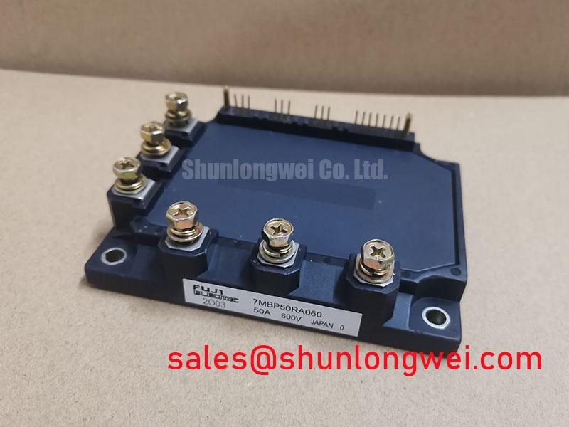
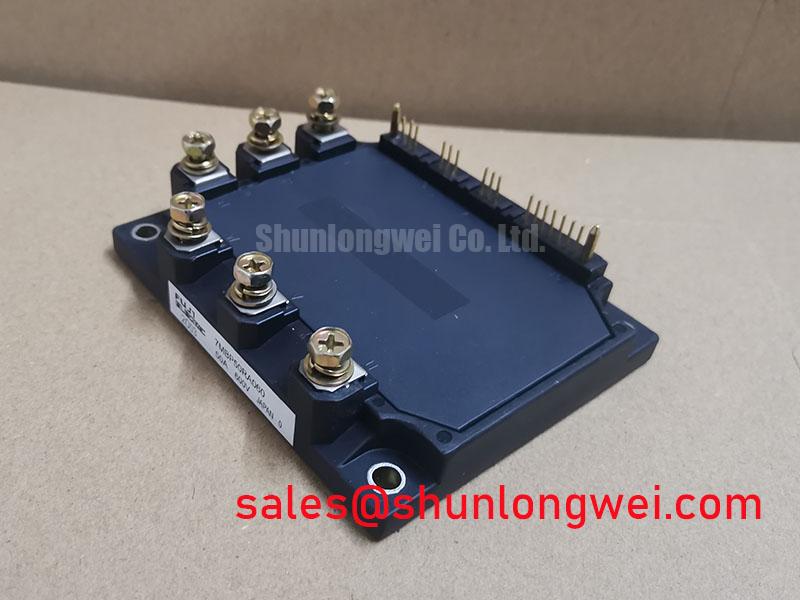
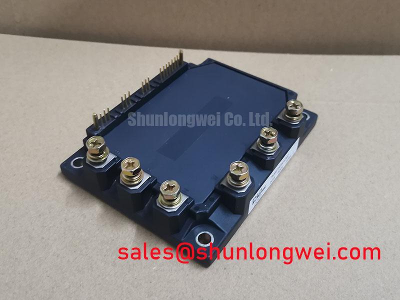
7MBP50RA060 | Manufacturer: Fuji Electric | Category: power module | Rated voltage: 600 V | Rated current: 50 A (Official Specification)
Capture the voltage at the module terminals during a controlled switching test and compare its turn-off peak with the 600 V rating of the 7MBP50RA060. A DC-link reading alone cannot establish the switching margin: current changing through stray inductance produces an additional voltage across the commutation path. Treat the measured peak, probe position and operating condition as a set. A trace taken at a distant bus capacitor can hide an excursion present at the module terminals.
The 600 V voltage and 50 A current ratings are Official Specifications, not targets for a busbar layout or permission to operate continuously at either limit. As a Design Consideration, keep the outgoing and returning current paths close and geometrically consistent so that the commutation loop does not introduce unnecessary inductance. Inspect the existing assembly for uneven busbar spacing, loose joints, changed capacitor connections and routing that forces one switching path to travel farther than its counterpart. Clearance, insulation and mechanical support must follow the equipment design rather than a dimension inferred from the module rating.
If a replacement drive shows a larger turn-off peak than a comparable working channel, first repeat the measurement with the same probe arrangement. Then compare the physical current paths and the condition of their joints. Snubber changes should follow measured waveforms: the system designer must assess both the overshoot and the losses introduced by a proposed network under the intended switching conditions. Pro tip: Keep paired busbar current paths geometrically consistent, then verify the resulting voltage margin at the module terminals during switching tests.
For a light industrial automation drive or multi-joint robotic articulator, confirm that the equipment schematic, terminal arrangement and control interface match 7MBP50RA060 before evaluating fit. The 7MBR10SA120-70 is a separate model that can be placed alongside the original documentation for comparison; its model name alone does not establish electrical or mechanical interchangeability. At the limits of an existing power stage, the switching-loss and layout discussion in Wide Bandgap Revolution provides broader context, not substitute ratings for this module.
7MBP50RA060 Thermal and Electrical Optimization: Heatsink Contact and Switching Response
Check the heatsink contact pattern when an otherwise comparable drive channel runs hotter at the same measured load. With power isolated and stored energy discharged, inspect the mating surfaces for debris, displaced thermal interface material and evidence of uneven seating. A temperature difference is a reason to inspect the entire heat path; it does not, by itself, identify the module as the cause.
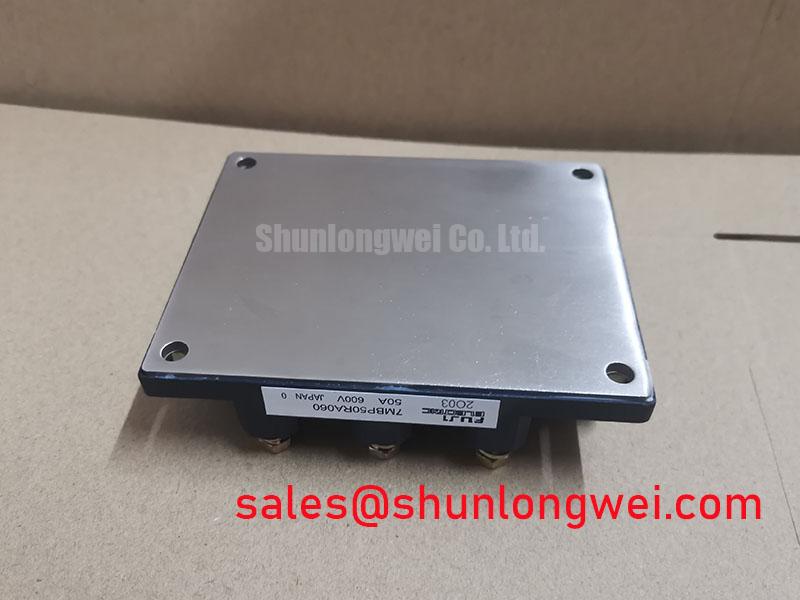
The product is supplied as a Fuji power module, but the supplied specifications do not establish a mounting torque, interface thickness or allowable baseplate curvature for this assembly. As a Design Consideration, use the equipment’s approved interface material and mounting procedure, apply it uniformly, and tighten the fasteners in the sequence specified for the mechanical design. Check that the heatsink is clean and adequately flat before mounting. Excess material can impede contact, while an interrupted contact pattern can make a temperature comparison misleading. Do not transfer a torque value from another package simply because its fasteners look similar.
Electrical heating deserves a separate measurement path. Compare load current, switching frequency and cooling conditions before attributing a hotter channel to poor heatsink contact. Where the equipment exposes suitable measurement points, examine the switching waveforms for unusually prolonged transitions or ringing. Drive behaviour, current-path inductance and freewheeling current can all affect the observed result. Record the test conditions so that a later waveform can be compared on the same basis.
A sharp voltage transition associated with diode recovery may prompt investigation of the commutation loop and snubber network, but it is not a diagnosis from a single trace. As a Design Consideration, inspect the return path and compare voltage and current waveforms before changing damping components. Snubber selection belongs to the system design: it must control the measured transient without imposing unacceptable loss or altering protection behaviour. For product-family context, Fuji Electric Power Semiconductor and IPM Modules describes the manufacturer’s power semiconductor portfolio; the host equipment documentation remains necessary for mounting and circuit-specific decisions.
7MBP50RA060 Operational Boundaries: PCB Return Paths and Drive Timing
Probe the control signal relative to its intended local return when a phase leg develops unexplained pulses or switching-edge oscillation. A measurement referenced to an arbitrary power-ground point may include voltage generated by current in a shared return path. Compare the signal at the controller output with the signal at the documented module input, using an appropriate isolated measurement method and the same operating state.
As a Design Consideration, keep sensitive control routing away from high-current switching paths and avoid making its return carry power-stage current. This is a PCB and wiring principle, not a claim that 7MBP50RA060 provides a particular auxiliary emitter or Kelvin terminal. Identify every control and power connection from the original circuit diagram before altering the harness. If the documented connections permit a separate local reference, preserve that intended route rather than joining it to a convenient, noisy point elsewhere on the board.
Inspect complementary control signals together when investigating suspected shoot-through. The relevant question is whether the outgoing device has ceased conducting before its counterpart is commanded on under the operating conditions being tested. Controller timing, internal drive delays and switching behaviour all contribute; the module’s 600 V and 50 A ratings do not specify a suitable dead time. As a Design Consideration, retain the equipment’s intended interlock and verify the available control and phase-node waveforms through commissioning. A commanded gap visible at the controller does not necessarily describe the switching timing at the module terminals.
Miller coupling also warrants attention if an inactive switch appears to turn on unexpectedly while the opposing device changes state. Compare the disturbance with a known-good channel before modifying external control routing or drive settings. The system designer should determine any change from the documented control interface and measured switching margins. If a fault occurs only with a long motor cable attached, inspect the voltage at the inverter output and the motor terminals: cable reflections can make those waveforms materially different. Filter selection must follow the cable, motor and drive documentation rather than a presumed property of this module.
Preventing Spurious Faults: Static and Dynamic Current Distribution
Compare current waveforms in each intended parallel path when a drive reports overcurrent during acceleration but carries a steady load without a fault. A balanced steady-state reading does not demonstrate balanced turn-on or turn-off. Use measurement locations and probes that make the paths comparable, and check whether the transient difference repeats at the same operating point.
Do not assume that a positive temperature coefficient of on-state voltage guarantees static current sharing for 7MBP50RA060. That behaviour must be established from the applicable device characteristics and operating region before it is used in a parallel-path analysis. As a Design Consideration, account for heatsink temperature differences, connection resistance and the actual current-path geometry when interpreting steady-state measurements. The 50 A Official Specification describes the module’s rated current; it does not certify a particular current split in an equipment-level parallel arrangement.
Dynamic sharing requires its own check because unequal control wiring or busbar paths can cause devices commanded together to switch at different moments. Trace each control path to its documented module connection, looking for mismatched routing, altered joints and shared return segments. Then compare the available control and power-terminal waveforms under controlled load conditions. If the traces differ, investigate the control and power paths before treating a trip indication as proof of a failed module.
When assessing 7MBP50RA060 for a robotic arm axis or another automation drive, close the evaluation against the host design rather than the model designation alone. Match the documented connections and package fit, measure switching peaks against the 600 V Official Specification, and check operating current and thermal conditions against the 50 A Official Specification. Resolve a transient imbalance with measured control and current-path evidence before returning the axis to service.