Content last revised on October 13, 2026
With the DC link discharged and verified safe, inspect the removed module’s mounting footprint before cleaning away the thermal compound: uneven transfer marks can help identify poor contact, trapped contamination, or distortion in the heatsink surface. For the 7MBP50TEA060, that inspection belongs alongside checking the equipment schematic, terminal assignments, and replacement mounting arrangement—not after the replacement has been tightened down.
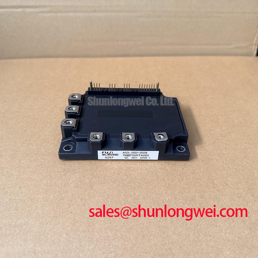
The Fuji Electric 7MBP50TEA060 has supplied official ratings of 600.0 V and 50.0 A, with the package identified as Fuji Power Module. These are product specifications, not suggested operating setpoints. A repair assessment should connect those ratings to the original machine’s power circuit, control interface, cooling arrangement, and protection behavior. The following installation and troubleshooting practices are Design Considerations, rather than additional manufacturer specifications.
7MBP50TEA060 Thermal-Electrical Optimization: Baseplate Convexity Compensation and Screw Practical Tuning
Inspect the heatsink contact face for raised burrs, embedded debris, and old compound before positioning the replacement module. A clean-looking surface can still have a local high spot that prevents even seating. Examine the module mounting surface without scraping, machining, or attempting to flatten it; any deliberate curvature must be evaluated against the manufacturer’s mechanical requirements rather than treated automatically as damage.
Thermal interface material fills surface irregularities between the module and heatsink. It should not become a structural spacer or a substitute for correcting an unsuitable mounting surface. As a Design Consideration, choose an application method that produces consistent coverage under the approved fastening procedure. The compound manufacturer’s instructions and the module assembly requirements should determine the application thickness; an arbitrary film thickness is not a verified specification for this model.
Before removal, photograph the compound transfer pattern on both mating surfaces. Areas with little transfer may indicate incomplete contact, while displaced accumulations can suggest uneven application or seating. Neither observation proves a particular internal fault. Compare the pattern with the mounting geometry, heatsink condition, and the equipment’s previous temperature behavior before deciding whether the interface contributed to shutdowns.
Where the assembly permits a trial fit, check seating without forcing the housing into alignment. Mounting holes should register naturally, and surrounding busbars or cables should not pull the module sideways. Mechanical stress introduced by a misaligned conductor can remain after the screws are tightened, making an apparently secure installation behave differently as the equipment warms.
Use the specified fastening sequence and torque for the actual module assembly. As an Engineering Recommendation, bring the fasteners into contact progressively and distribute clamping evenly instead of fully tightening one corner while the others remain loose. Screw size alone does not establish permissible torque: thread engagement, washers, the heatsink material, and the module mounting structure all affect the joint.
Field Alert: Do not use mounting screws to pull a misaligned module or busbar into position; correct the fit before applying the approved tightening procedure.
Keep mounting-screw requirements separate from power-terminal fastening requirements. A terminal joint needs secure electrical contact without transferring excessive load into the housing. Inspect mating conductors for flatness and contamination, support heavy busbars independently where the equipment design provides for it, and preserve the original clearances around adjacent conductors.
After installation, evaluate cooling performance under a controlled load progression established for the equipment. Observe the accessible module or heatsink temperature together with load current, cooling airflow, and ambient conditions. A rising temperature trend can involve interface contact, fan performance, heatsink fouling, or operating losses; it should not be attributed to thermal compound alone. Keep measurement locations consistent when comparing before-and-after results.
Pressure-contact spring stacks and double-sided cooling arrangements should not be introduced merely because they appear in other power semiconductor assemblies. The package designation supplied for the 7MBP50TEA060 does not establish either construction. Preserve the approved mounting architecture, including the original mechanical support and cooling path, rather than adapting an unrelated clamping method.
Transient Dynamics & Electrical Design: Driver Power Stage Start-Up Inrush Mitigation on 7MBP50TEA060
Capture the control-supply startup and switching-enable sequence before attributing an immediate trip to the replacement module. Check whether the controller maintains a defined disabled state while the relevant supply rails establish themselves, and whether a brownout produces orderly shutdown rather than repeated enable attempts. Use appropriately rated, isolated measurement equipment for floating power-stage references.
Driver auxiliary-supply startup and DC-link charging are separate events. As a Design Consideration, distinguish charging current in the link capacitors from current associated with unintended power-stage switching. Check the precharge circuit, its bypass control, and the controller’s enable sequence individually. A fault indication during energization can originate in any of these paths, so its timing is more informative than the indication alone.
Do not apply a generic negative gate-bias range or external gate-resistor prescription to this module. Gate-drive arrangements must follow the actual module interface and the equipment schematic. Where drive functions are integrated, the service task concerns the permitted control inputs, auxiliary supplies, and fault outputs; changing an external control-input resistor is not equivalent to tuning a discrete IGBT gate circuit.
For circuits that expose an external gate-drive connection, sourcing and sinking capability should be assessed against the switching device requirements and the intended switching behavior. Gate-loop damping balances oscillation control against switching loss and transition speed. Those are general engineering principles, not evidence that the 7MBP50TEA060 accepts an external gate resistor or requires a particular turn-off voltage.
Fuji Electric’s High-Speed Discrete IGBTs information provides manufacturer context for discrete-device switching technology. Its relevance here is conceptual: discrete gate-drive practices should not be transferred automatically to an integrated module. For topology comparisons, Fuji Electric’s PIM 7-Pack information describes a separate module family, rather than establishing this model’s terminal functions.
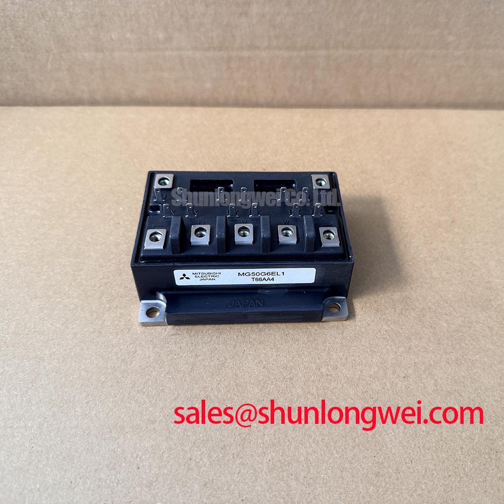
Engineers evaluating the 7MBP50TEA060 for a compact industrial inverter or high-speed CNC spindle drive should compare the original assembly’s complete electrical and mechanical interface. The related 7MBR50SB120-60 can serve as a comparison reference, but the shared manufacturer and similar part-number elements do not establish interchangeability.
| Comparison item | 7MBP50TEA060 | 7MBR50SB120-60 |
|---|---|---|
| Manufacturer | Fuji Electric | Fuji Electric |
| Rated voltage | 600.0 V — Official Specification | Consult Datasheet |
| Rated current | 50.0 A — Official Specification | Consult Datasheet |
| Package designation | Fuji Power Module | Consult Datasheet |
| Replacement assessment | Match terminal functions, control interface, mounting, and cooling | Establish the same interfaces independently before considering substitution |
Trace the incoming rectifier, DC-link storage, braking circuit, and inverter stage separately when reviewing the machine architecture. The 7MBR50SB140 is another module reference for that topology review, not an assumed upstream rectifier or a prescribed companion to the 7MBP50TEA060. Functional placement must come from the circuit diagram.
For an existing MOV or other overvoltage-absorption network, inspect its connections and condition, then evaluate its role in the original protection scheme. As a Design Consideration, switching overshoot depends on the commutation path as well as the absorption network. Preserve short, well-controlled current loops and measure switching peaks under defined conditions; adding an absorber without assessing repetitive stress and protection coordination is not a complete repair.
Control-board isolation also deserves attention when fault signals coincide with switching edges. Evaluate optocoupler or digital-isolator common-mode transient immunity against the actual switching environment, and examine local supply disturbance and signal-return routing. If the original driver uses a bootstrap supply, assess its recharge opportunities, capacitor condition, and diode behavior against the operating sequence. Neither circuit arrangement should be assumed from the module number.
7MBP50TEA060 Operational Boundaries: Evaluating Substrate Micro-Crack Screening Limits
Separate the module from connected electronics before considering an insulation test, and establish the permitted terminal grouping, test voltage, and acceptance criteria from the applicable manufacturer procedure. A high-voltage tester connected through a driver board or sensing circuit can stress components that were never intended to receive that test.
Terminal-to-baseplate insulation screening evaluates electrical isolation under the prescribed conditions; it does not directly reveal an internal ceramic crack. The supplied specifications do not establish a particular substrate construction or a model-specific micro-crack acceptance limit. Keep the inspection focused on observable housing condition, contamination, mounting damage, and valid electrical measurements rather than assigning an unseen internal defect.
As a Design Consideration, remove conductive dust and moisture using a process compatible with the assembly materials. Inspect accessible insulation surfaces around terminals and mounting features for deposits, tracking marks, or mechanical damage. Preserve the equipment’s intended clearances, barriers, and conductor routing; a universal spacing value cannot replace an assessment of the actual voltage, environment, and assembly geometry.
If an isolation measurement appears abnormal, check the test setup and external leakage paths before interpreting the result. Connected wiring, contaminated surfaces, fixtures, and adjacent components can affect the reading. Repeat measurements only under the authorized procedure, recording the connection arrangement and environmental conditions so that results remain comparable.
Cold resistance and diode-mode checks can help identify a gross power-path anomaly when performed against the verified terminal diagram. Compare equivalent paths using the same instrument and connection method, preferably against a known-good assembly. An asymmetric reading calls for further investigation; it does not, by itself, distinguish semiconductor damage from a parallel circuit path or establish a precise failure mechanism.
The Power Electronics Masterclass offers broader engineering context for selection and system reliability. For this repair, retain the narrower evidence set: correct interfaces, sound mounting, valid isolation checks, stable startup behavior, and measured operating conditions. These observations support an installation decision without turning a workshop inspection into a lifetime or insulation-reliability guarantee.
Before returning the equipment to service, remove test connections, restore protective covers and grounding, and confirm that fault reporting remains functional. Apply the equipment’s controlled commissioning procedure while observing supply behavior, load current, and temperature. If a trip recurs, preserve the waveform and event timing before changing another component; that record helps separate a switching disturbance, control-supply interruption, and load-related event.