Content last revised on October 2, 2026
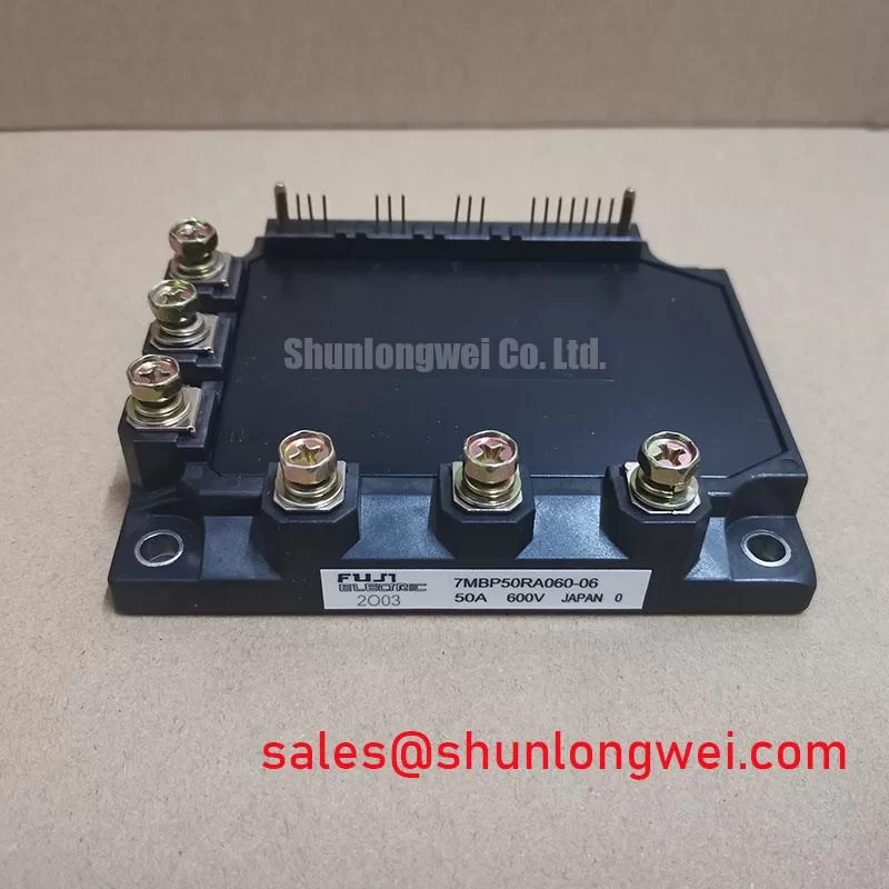
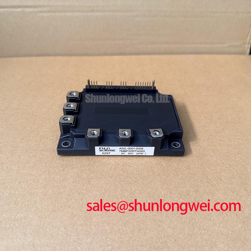
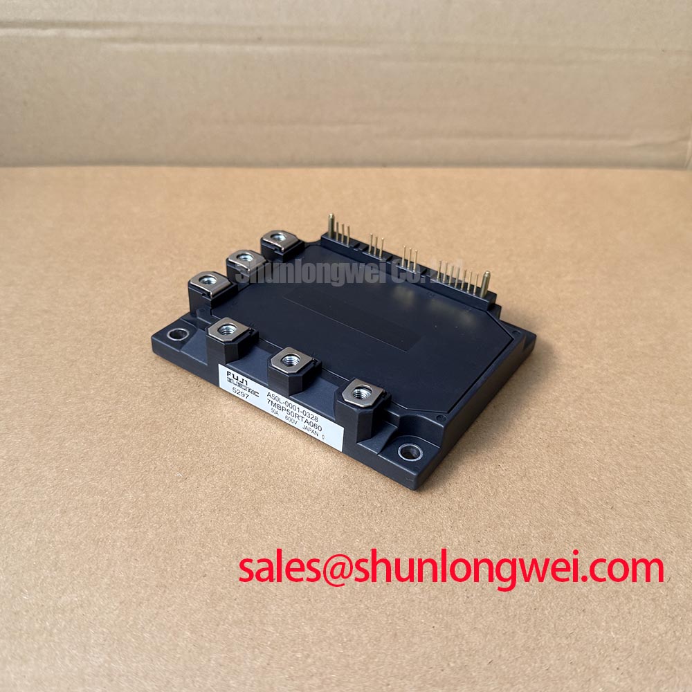
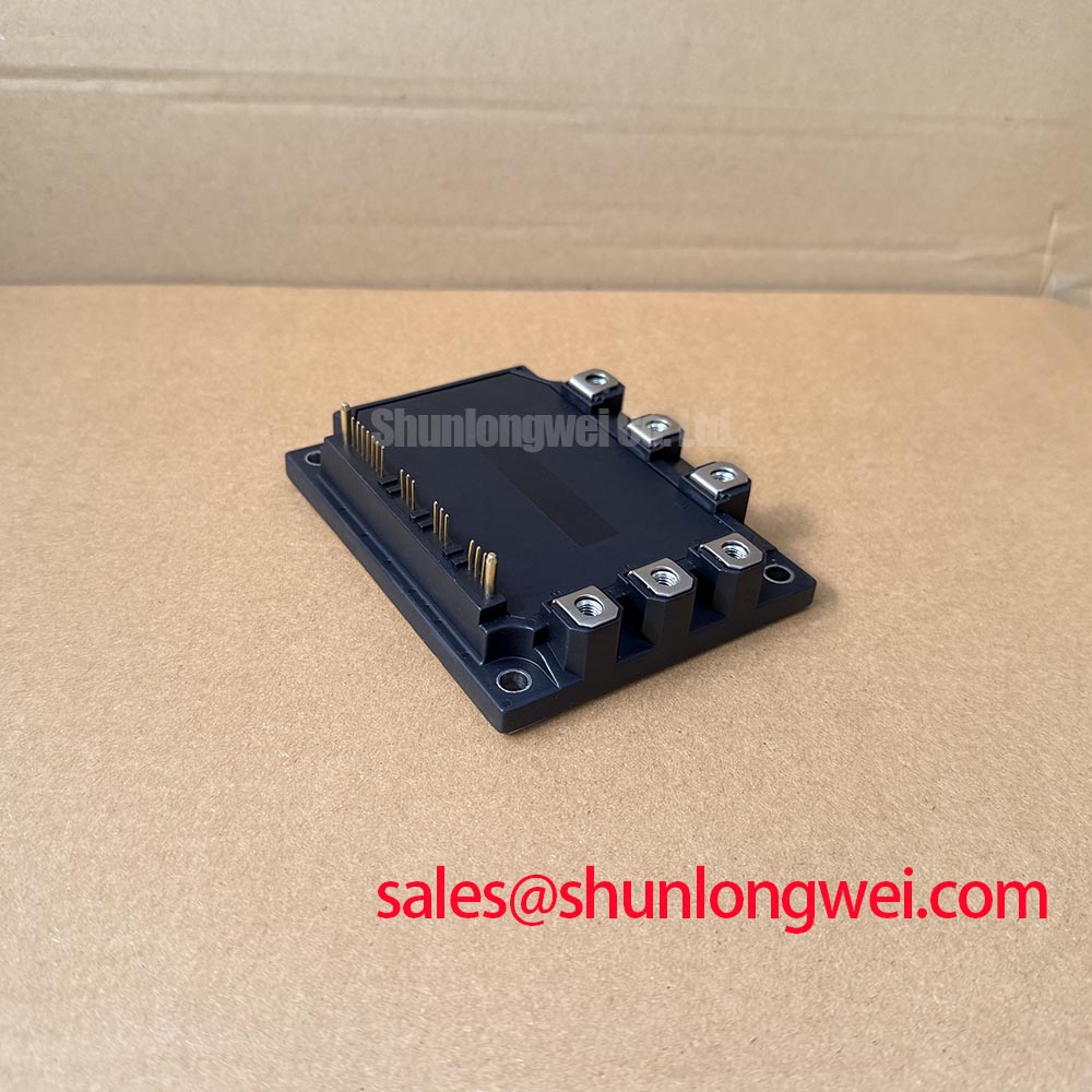
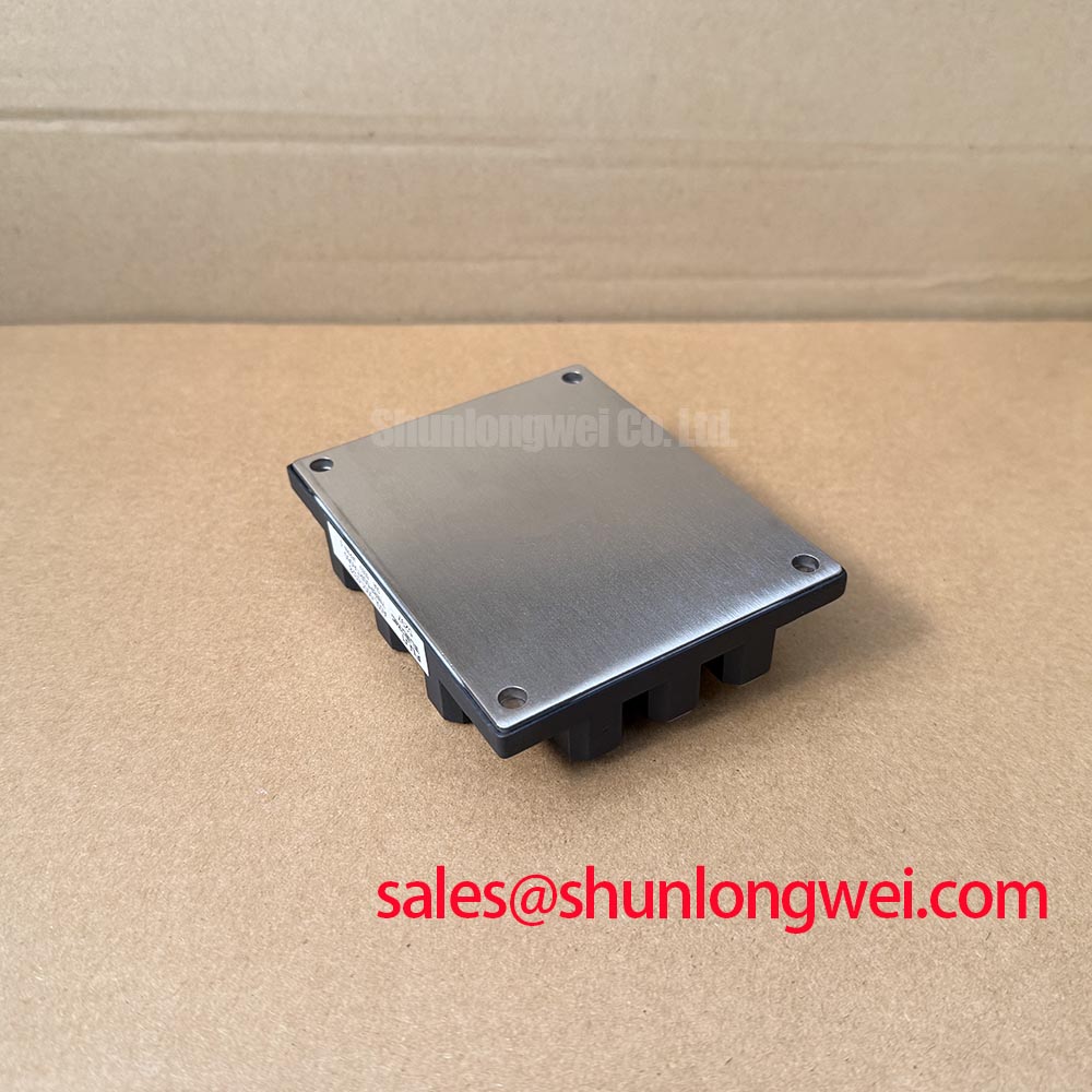
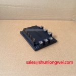
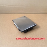
7MBP50RTA060 Fuji Electric 600V 50A Intelligent Power Module
Start a bench inspection by isolating the drive, confirming the nameplate rating, and checking the power terminals for abnormal cold-state impedance before reconnecting the DC link. The 7MBP50RTA060 is a Fuji Electric power module with a rated voltage of 600.0 V and a rated current of 50.0 A.
| Parameter | Official Specification |
|---|---|
| Manufacturer | Fuji Electric |
| Part number | 7MBP50RTA060 |
| Product category | Intelligent Power Module (IPM) |
| Rated voltage | 600.0 V |
| Rated current | 50.0 A |
| Package | Module |
These values are the available product data for identification and first-stage compatibility review. They do not replace the complete Fuji Electric documentation required for switching frequency, junction-temperature limits, control-input behavior, protection functions, isolation ratings, terminal arrangement, or thermal derating. A service engineer should verify those conditions against the original equipment documentation before applying power.
In high-dynamics multi-axis CNC equipment and robotics servo drives, the module is normally evaluated as part of a complete inverter power stage rather than as an isolated replacement. The surrounding control circuitry, DC-link arrangement, motor cable length, cooling assembly, control firmware, and fault protection all influence whether the replacement is electrically suitable.
Field Diagnostics & Commissioning: Switching and Drive-Signal Integrity for 7MBP50RTA060
After the equipment is locked out, begin with a visual inspection of the module body, power terminals, control connector area, mounting surface, and nearby control components. Look for cracked insulation, discolored terminals, loose hardware, damaged conductor insulation, or evidence that the heatsink has shifted. Do not interpret a single resistance reading as proof that the module is serviceable. Compare measurements between corresponding power paths and, where available, against a known-good assembly with the same circuit topology.
Use a properly isolated meter and keep the DC bus fully discharged before checking terminal impedance. The test should be performed with the module disconnected from surrounding circuitry whenever the equipment procedure permits, since parallel resistors, snubber networks, sensing circuits, and semiconductor protection paths can influence the reading. A reading that differs materially from the matching phase should trigger a wider inspection of the control board and bus structure rather than an immediate single-cause diagnosis.
Official Specification: the 7MBP50RTA060 is rated at 600.0 V and 50.0 A; these ratings are identification data, not permission to operate the complete inverter at those limits without checking the relevant switching, thermal, and transient conditions.
Switching-signal integrity becomes especially important when a servo amplifier changes state quickly. Parasitic capacitance between power and control nodes can couple a switching transient into control circuitry. If a control return path is long, shared with high-current commutation paths, or routed close to the output conductors, measured signals may show ringing or unintended transitions. Such behavior warrants investigation, but the actual cause must be established through measurements appropriate to the module’s accessible terminals and the equipment design.
As a Design Consideration, keep accessible control-signal return paths short and separated from high-current commutation paths. Gate resistors, an active Miller clamp, or negative gate bias should not be added to an intelligent power module by assumption; internal gate-drive arrangements and access to gate-emitter nodes must be verified from the applicable Fuji Electric documentation. Any external control circuitry should be evaluated against the module’s specified interface requirements.
When a servo axis trips during acceleration or deceleration, capture the accessible control signals, phase-node waveform, DC-link waveform, and control supply where the equipment provides suitable measurement points. This helps separate a control disturbance from DC-link collapse, current-sensor error, control timing loss, or motor-cable reflection. Measurements should be made with probes rated for the switching environment and connected according to the probe manufacturer’s common-mode and insulation requirements.
For control-loop routing, return-current control, and switching waveform review, engineers can consult Precision Gate Drive Design as a related engineering reference. Its gate-drive guidance should be applied only where the module and equipment architecture permit it.
Assembly Integrity & Layout Architecture: Optimizing Heatsink Contact Pressure for 7MBP50RTA060
Thermal assembly errors can remain hidden during a short bench test and appear later as current imbalance, protection trips, or progressive temperature rise. Before installing a replacement, remove old interface material from the heatsink and inspect the surface for burrs, contamination, unevenness, or local damage. The module base and heatsink must meet the mechanical flatness and surface requirements stated in the applicable Fuji Electric installation documentation.
Thermal interface material should be applied evenly and only in the quantity required by the approved assembly method. Excess compound can migrate toward the module edge or contaminate nearby insulation surfaces, while insufficient coverage can leave air gaps beneath the base. The correct interface material, application method, and permitted thickness are system and manufacturer dependent; they should not be inferred from a generic module installation guide.
Mounting screws should be tightened in the specified sequence and to the torque required for the actual hardware and module assembly. Tightening one corner completely before the others can distort contact pressure and reduce cooling consistency. After mounting, verify that the module is seated without visible rocking and that the busbar or cable connections do not impose mechanical force on the terminals.
Field Alert: disconnect the drive and verify the DC link is discharged before inserting or removing control and power connections, and use only the mounting torque and sequence specified for the actual assembly hardware.
From a layout perspective, keep high-current commutation loops compact and separate sensitive control traces from phase-output conductors. The objective is to reduce parasitic coupling and uncontrolled voltage overshoot; the final clearance, creepage, conductor geometry, and insulation system must be determined from the working voltage, pollution environment, enclosure design, and applicable equipment standard.
Where a design provides an accessible gate-drive stage and permits external gate-resistance adjustment, resistance is a tuning element, not a universal fixed value. Increasing resistance can reduce edge speed and ringing in some circuits, while excessive resistance can increase switching loss or interfere with the protection timing. Decreasing it can sharpen transitions but may increase overshoot and electromagnetic disturbance. Any adjustment should follow the module and equipment documentation and be checked through controlled waveform and fault-response testing.
For a CNC or robotics servo installation, also inspect the mechanical relationship between the module, heatsink, busbars, and cabinet structure. Vibration transmitted through a rigid busbar can stress power terminals even when the electrical connections appear tight. Cable supports should prevent the motor cable and DC-link conductors from pulling directly on the module terminal area.
Where the original service design permits evaluation of a related Fuji Electric module, the 7MBR50LC060 may be reviewed as a separate compatibility candidate. It should not be treated as a drop-in substitute until terminal arrangement, electrical ratings, control-interface requirements, protection behavior, mechanical dimensions, and the equipment manufacturer’s documentation have all been checked.
Field Diagnostics & Commissioning: Transmission-Line Impedance Mismatch in 7MBP50RTA060 Topologies
Long motor leads can behave as a distributed electrical network rather than a simple load. When the inverter edge reaches the motor terminals, impedance differences between the cable, motor winding, connectors, and termination can produce reflections. The resulting waveform may show overshoot or ringing at the inverter output and motor end. The severity depends on cable construction, length, switching behavior, grounding, motor impedance, and the complete drive topology, so a general voltage multiplication claim should not be applied to every installation.
When a repaired servo drive shows a repeatable overvoltage trip, inspect the output waveform with a suitable high-voltage differential probe at both the inverter and motor terminals when the measurement setup allows it. Check the motor cable shield termination, protective-earth bonding, connector condition, and cable routing alongside control and encoder wiring. A waveform observed only at the inverter may not reveal the stress appearing at the motor terminals.
Output chokes, dv/dt filters, sine-wave filters, and other motor-side components can reduce stress in some systems, but the appropriate device depends on the drive switching behavior, motor insulation system, cable characteristics, control response, and thermal loss. The filter must be evaluated for resonance, voltage drop, current capability, leakage current, and compatibility with the servo control loop. It should not be selected from the 7MBP50RTA060 current rating alone.
During commissioning, record the DC-link voltage, phase output waveform, accessible control signals, motor current, and fault log under the same acceleration and deceleration profile that produces the field symptom. If the problem changes when the cable route or motor is changed, that observation may indicate a system-level interaction rather than a defective module. If the symptom remains with the motor disconnected and a controlled load connected, inspect the inverter layout, snubber network, control circuitry, and DC-link structure.
Clearance and creepage around the power terminals should be reviewed after any field modification. Dust, coolant residue, conductive debris, and damaged insulating barriers can change the effective electrical environment. The required spacing is determined by the working voltage, overvoltage category, pollution degree, material characteristics, altitude, and applicable safety standard. These values should come from the equipment design documentation rather than from a generic replacement listing.
The 7MBP50RTA060 identification should be cross-checked against the failed unit, the drive schematic, the terminal configuration, and the control-board interface before energization. A matching current and voltage label does not by itself confirm pin compatibility or protection compatibility. The commissioning engineer should also verify phase sequence, current-sensor polarity, brake resistor wiring, encoder feedback, and the inverter’s fault-clear procedure.
Assembly Integrity & Layout Architecture: Reinforced Insulation Barrier Integrity for 7MBP50RTA060
Isolation must be reviewed across the complete drive assembly, including the power module, control supply, control board, communication interface, heatsink, motor cable, and cabinet bonding. The available product data identifies the 7MBP50RTA060 as a 600.0 V, 50.0 A Module, but that data does not establish a reinforced-insulation withstand rating or a common-mode transient immunity value for the complete system. Those properties must be confirmed from the applicable Fuji Electric documentation and the relevant isolation component data.
In a multi-axis servo cabinet, common-mode voltage can couple through heatsinks, cable shields, encoder wiring, and control-board capacitance. A fault signal, enable line, or isolated communication channel may respond differently from the power-stage switching event. During troubleshooting, compare the accessible control supply, input command, fault feedback, and switching waveforms with an oscilloscope that is suitable for the common-mode voltage present.
Do not assume that an isolated component automatically provides reinforced insulation for the complete equipment. The insulation barrier must be supported by PCB spacing, slot geometry, isolation components, connector ratings, mounting hardware, contamination control, and enclosure construction. The system designer should evaluate these features against the required safety classification and applicable certification plan.
Spurious switching or fault behavior can also be associated with a weak control supply, an incomplete return path, excessive parasitic coupling, incorrect command timing, or a control signal that is not referenced as intended. Check the control supply at the designated measurement points during switching, inspect the isolation barrier for contamination or damage, and compare the command and feedback timing across all axes. Avoid replacing the power module before these surrounding conditions have been tested.
For equipment exposed to vibration, inspect the insulating washers, standoffs, busbar supports, connector locks, and cable clamps during every service intervention. Mechanical movement can enlarge a clearance gap, loosen a terminal, or transfer stress into a control connector without leaving an obvious mark on the module body. The final insulation verification method, test voltage, and acceptance criteria must follow the equipment manufacturer’s service procedure and the relevant safety standard.
After replacement, use a staged commissioning process: verify the mechanical installation with power removed, confirm the isolation and continuity checks required by the service manual, energize the control supply without enabling the power stage when possible, and then perform a controlled low-demand motion test. Monitor phase current, fault feedback, temperature behavior, and accessible switching waveforms before returning the CNC axis or robot servo to production duty.