


Content last revised on June 20, 2026
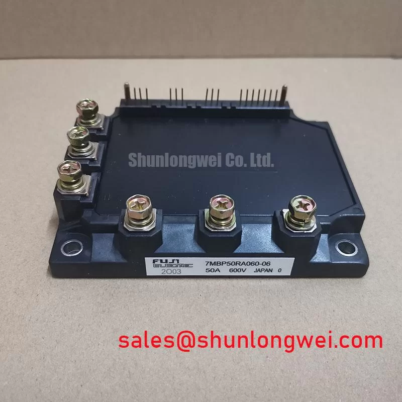
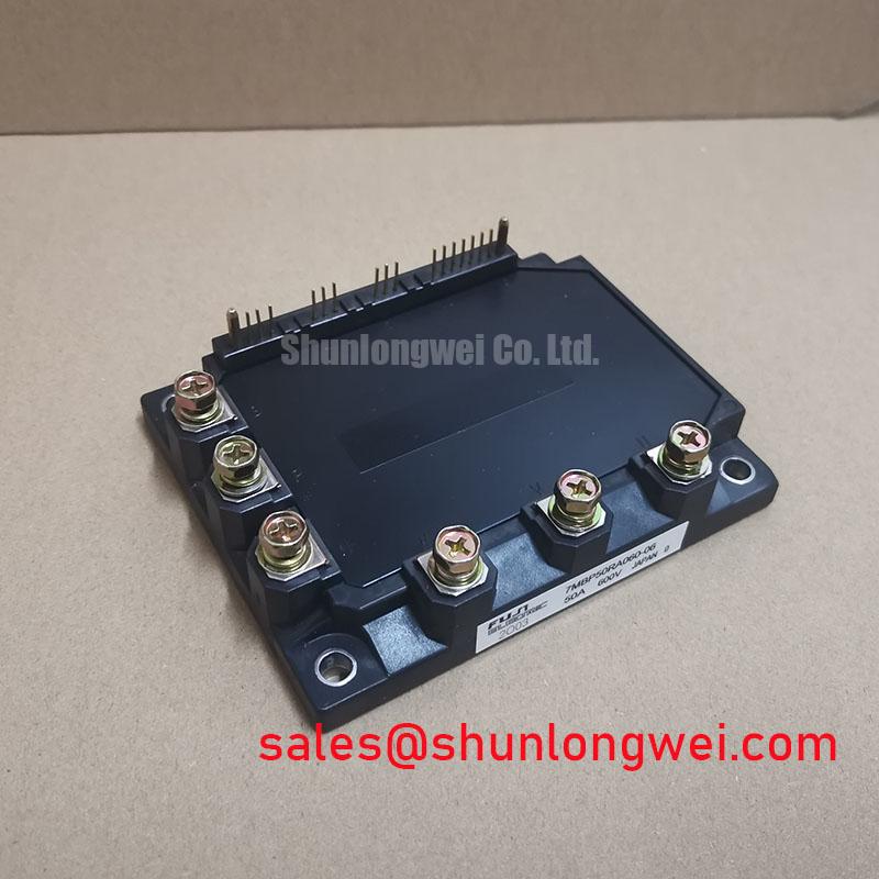
7MBP50RA060-06: 600V 50A 7-in-1 PIM for Reliable Motor Drives
An Integrated Power Stage for Compact, Thermally-Efficient Systems
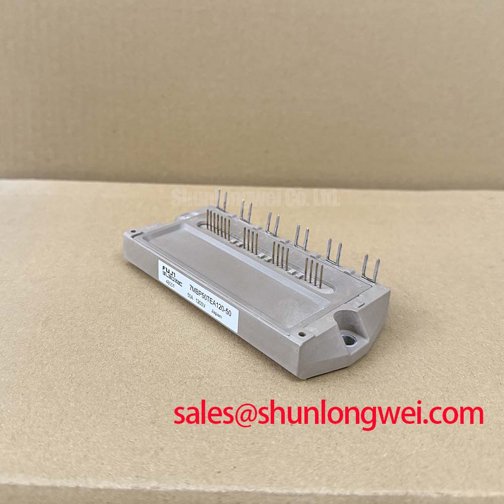
This 7-in-1 Power Integrated Module (PIM) streamlines the design of compact motor drives by integrating key thermal management features directly into the power stage. With core specifications of 600V | 50A | 7-in-1 Configuration, the Fuji Electric 7MBP50RA060-06 delivers tangible engineering benefits, including a simplified thermal design and a significantly reduced system footprint. It integrates a full three-phase inverter, brake chopper, and rectifier, dramatically reducing external component count and simplifying assembly for low-power AC motor control. For compact servo drives under 7.5kW requiring precise thermal monitoring, the 7MBP50RA060-06 offers an optimal, integrated solution.
Application Scenarios & Value
Streamlining Compact Motor Drive Design with Integrated Thermal Management
The 7MBP50RA060-06 is engineered to solve the core challenges of power density and thermal management in space-constrained industrial applications. Its primary value is in simplifying the power stage of low-to-medium power AC motor drives, making it an ideal component for systems such as CNC machine servo drives, robotics, automated material handling systems, and small general-purpose inverters.
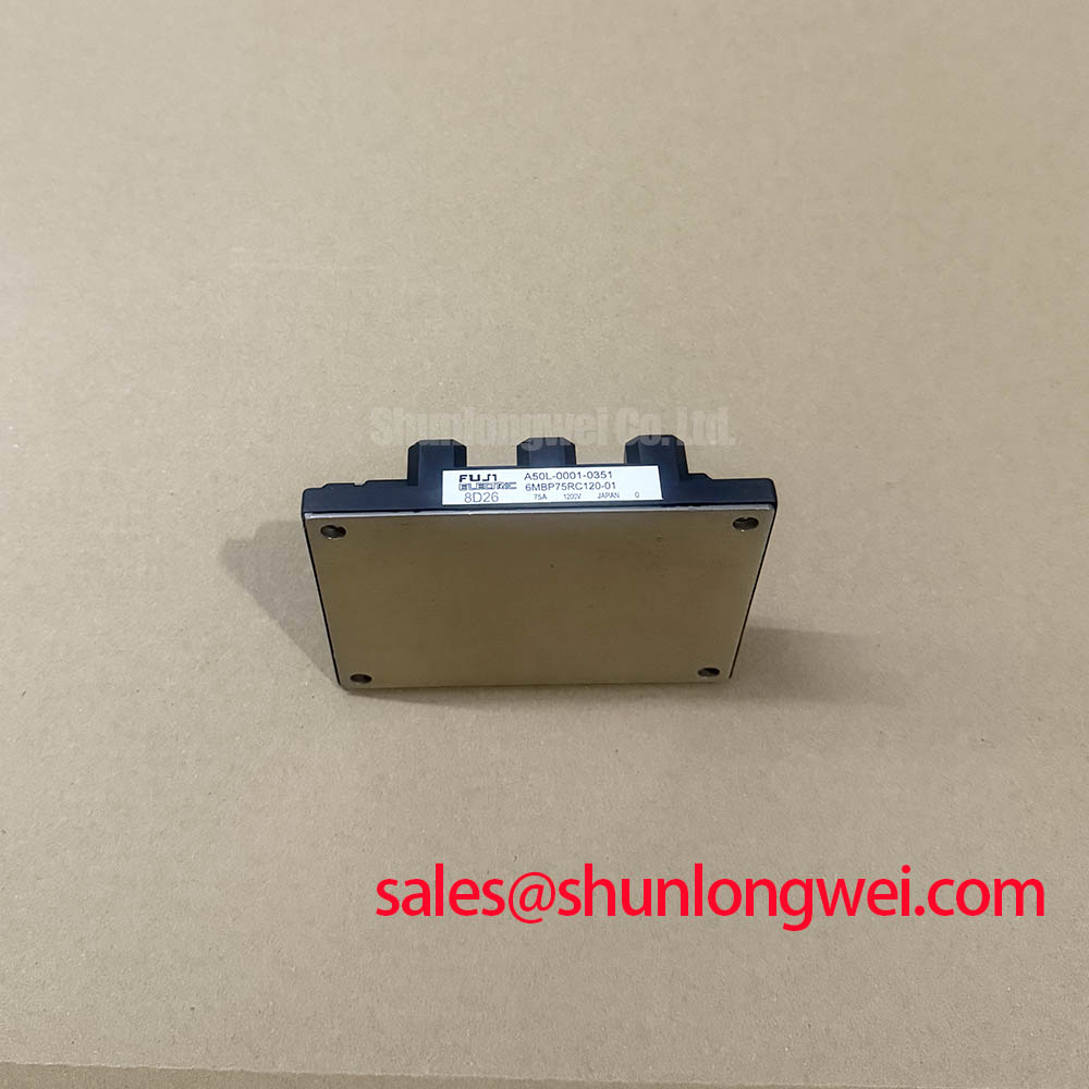
Consider the engineering challenge of designing a servo drive for a robotic arm, where the control cabinet is compact and airflow is limited. The high integration of the 7MBP50RA060-06—combining the converter, brake, and inverter circuits into one P626 package—immediately reduces PCB space and assembly complexity. More critically, its low thermal resistance from junction to case (Rth(j-c)) allows for the use of a smaller, more cost-effective heatsink. This parameter acts like the diameter of a pipe for heat; the lower the value, the more efficiently heat escapes the semiconductor die, preventing thermal throttling and improving long-term reliability. The module's built-in NTC thermistor provides the direct, real-time temperature feedback necessary to implement sophisticated Over-Temperature Protection (OTP), ensuring the drive operates safely under demanding load cycles.
This level of integration provides a distinct advantage over discrete designs, reducing component count, minimizing potential points of failure, and accelerating the time-to-market. For applications demanding higher output power within a similar architecture, the related 7MBP75RA060 provides a 75A capability.
Key Parameter Overview
Critical Specifications for Power Stage and Thermal Design
The technical specifications of the 7MBP50RA060-06 are tailored for robust performance in 200-240V AC line applications. The following table highlights the key parameters derived from the official datasheet, with a focus on values critical for both electrical and thermal design decisions.
| Parameter | Symbol | Condition | Value |
|---|---|---|---|
| Collector-Emitter Voltage | Vces | Tj = 25°C | 600 V |
| Continuous Collector Current (DC) | Ic | Tc = 80°C | 50 A |
| Collector-Emitter Saturation Voltage | VCE(sat) | Ic = 50A, Tj = 125°C | 2.2 V (Typ) / 2.7 V (Max) |
| Thermal Resistance (IGBT) | Rth(j-c) | Junction to Case | 1.7 °C/W |
| Thermal Resistance (FWD) | Rth(j-c) | Junction to Case | 2.5 °C/W |
| NTC Thermistor Resistance | R25 | T = 25°C | 50 kΩ ± 5% |
| Maximum Junction Temperature | Tjmax | - | 150 °C |
Download the 7MBP50RA060-06 datasheet for detailed specifications and performance curves.
Technical Deep Dive
Leveraging the Integrated NTC Thermistor for Enhanced System Reliability
While many power modules feature over-temperature protection, the direct integration of an NTC thermistor within the 7MBP50RA060-06 provides a more precise and proactive method of Thermal Management. This component is not merely a trip switch; it is a sensor that provides a continuous, analog representation of the module's internal temperature.
The thermistor's resistance changes predictably with temperature, as defined by the R-T curve in the datasheet. A microcontroller in the drive's control logic can continuously monitor this resistance, calculate the real-time die temperature, and make intelligent decisions. This enables a tiered protection strategy. For instance, the system can trigger a warning and reduce motor output current at 125°C, and only initiate a full shutdown if the temperature continues to rise towards the 150°C Tjmax limit. This proactive derating prevents unnecessary downtime while protecting the module from catastrophic failure.
To draw an analogy, the integrated thermistor is like a modern car's engine temperature gauge, providing the driver (the control system) with continuous data. This allows them to ease off the accelerator (reduce motor current) before the engine overheats, rather than just relying on a simple warning light (a basic thermal switch) that only activates when a critical temperature is already reached. This feature is fundamental to designing a truly robust and reliable Variable Frequency Drive (VFD).
Frequently Asked Questions
Engineering Inquiries on the 7MBP50RA060-06
How does the integrated NTC thermistor in the 7MBP50RA060-06 improve servo drive reliability over external temperature sensors?
An integrated NTC thermistor provides a more accurate measurement of the IGBT junction temperature because it is located much closer to the heat source (the silicon die) than an external sensor placed on the heatsink or module case. This reduces thermal lag and measurement error, allowing for faster and more precise responses to thermal events, which directly enhances the reliability and safety of the servo drive.
What is the primary benefit of the '7-in-1' configuration for a system designer?
The primary benefit is system simplification. By integrating the three-phase rectifier, brake chopper, and three-phase inverter into a single module, it drastically reduces the number of high-power components, simplifies the PCB layout, shortens assembly time, and minimizes parasitic inductance between stages. This leads to a smaller, more cost-effective, and often more reliable final product.
Does the VCE(sat) of 2.2V (typ) impact thermal design, and how?
Yes, VCE(sat) is a critical parameter for thermal design as it directly determines conduction losses (Power Loss = VCE(sat) x Ic). A lower VCE(sat) means less heat is generated during operation for a given current. The typical value of 2.2V at 50A signifies efficient performance, directly contributing to lower overall power dissipation and reducing the burden on the cooling system.
What are the key considerations when selecting a heatsink for this module, given its Rth(j-c) of 1.7 °C/W?
The Rth(j-c) of 1.7 °C/W (for the IGBT) is the starting point for thermal calculations. To select an appropriate heatsink, an engineer must first calculate the total power dissipation based on conduction and switching losses for their specific application. The goal is to choose a heatsink with a thermal resistance (Rth(c-a)) low enough to ensure the maximum junction temperature (Tjmax) of 150°C is not exceeded under worst-case ambient temperature and load conditions. The low Rth(j-c) of this module provides a good thermal budget, potentially allowing for a smaller heatsink compared to modules with higher thermal resistance.
Strategic Fit for Modern Industrial Automation
In a market driven by demands for higher efficiency, smaller footprints, and faster development cycles, the 7MBP50RA060-06 represents a strategic choice for design engineers. By integrating the complete power conversion and braking stage with essential thermal monitoring, this Power Integrated Module (PIM) allows engineering teams to focus on higher-level control logic and software, rather than the complexities of power stage layout and thermal interfacing. This translates directly into a competitive advantage, enabling the creation of more compact, reliable, and cost-effective industrial automation solutions.