





Content last revised on September 30, 2026
6MBI50VA-120-50 Circuit Protection & Reliability: Checking the Active Miller Clamp
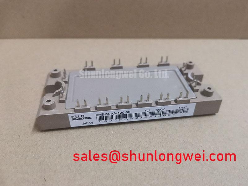
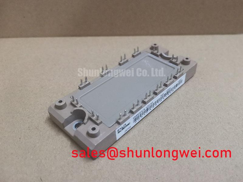
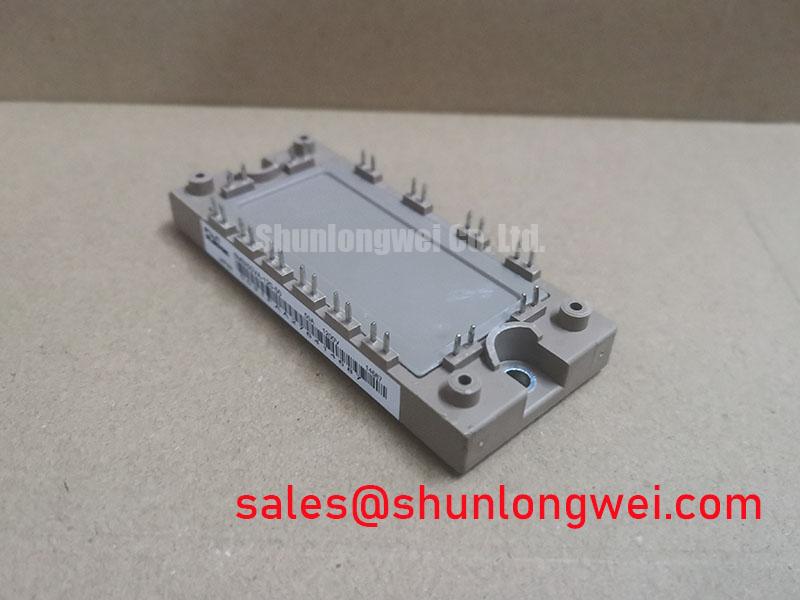
6MBI50VA-120-50 | Manufacturer: Fuji Electric | Category: IGBT module | Package: Fuji Power Module | Rated voltage: 1200 V (Official Specification) | Rated current: 50 A (Official Specification)
With the module isolated, compare the cold diode-mode readings across corresponding power terminals before energizing a replacement drive. A reading that differs sharply from an established, known-good baseline warrants investigation, but diode mode alone cannot establish switching health. Match each terminal to the equipment wiring diagram rather than inferring its function from terminal position; record probe polarity and readings so the comparison can be repeated after installation.
A gate voltage rise during the opposite switch’s turn-on can point to Miller coupling through the gate-to-collector capacitance. That observation does not, by itself, prove a defective 6MBI50VA-120-50. As a Design Consideration, inspect the driver’s active Miller clamp path, its connection to the gate reference, and the gate-loop layout. A low-impedance clamp can help hold the commanded-off device off during a fast switching transition, provided the driver enables it at the appropriate point in the turn-off sequence. Negative gate bias is another driver-level option, not a specified operating requirement for this module; its level and compatibility belong to the system design.
Capture gate-to-emitter voltage at the module terminals during controlled switching, using measurement practice suited to the circuit’s voltage and common-mode environment. Compare the off-state trace with the opposite switch’s transition and the driver’s clamp indication, if accessible. Ringing that changes when the probe ground path changes may be a measurement artifact; ringing that persists calls for inspection of the gate return, connections, and damping arrangement. As an Engineering Recommendation, keep the gate and return paths closely coupled to limit parasitic-loop effects, then verify the result under the drive’s actual switching conditions. Fuji Electric’s V-Series IGBT Application Manual provides manufacturer-level application context for gate-drive and protection review.
💡 Bench Tip: Discharge the drive and protect exposed gate terminals from electrostatic handling before taking cold readings.
Transient Dynamics & Electrical Design: Checking Peak Junction Temperature on 6MBI50VA-120-50
Log the case-temperature response and load-current waveform during a controlled overload test; a steady temperature reading can conceal a hotter junction during a short pulse. The 50 A rating is an Official Specification, not permission to apply every pulse shape at that current without checking temperature limits and cooling conditions. Record the pulse duration, repetition pattern, DC-link voltage, switching frequency, and measured case temperature together. Those conditions determine whether a thermal comparison is meaningful.
For an Engineering Calculation, apply switching and conduction losses for the measured operating points to an appropriate transient junction-to-case thermal-impedance model, then add the measured case temperature to estimate peak junction temperature. A multi-RC model can represent how the junction responds across different pulse durations, but model coefficients, loss data, and permissible junction-temperature limits must come from applicable manufacturer documentation rather than being invented for this part. Compare the calculated peak with the documented limit and repeat the check when the heatsink, mounting interface, or switching pattern changes.
Trace the heat path during incoming and post-repair checks. Uneven contact, disturbed thermal-interface material, or inconsistent fastening can change the observed case response without changing the module’s nameplate ratings. As a Design Consideration, use the equipment’s mounting instructions to assess contact and tightening; do not substitute a generic torque value for its assembly specification. If the measured case temperature rises unexpectedly, check airflow and heatsink contact alongside electrical losses instead of treating either as the sole cause.
Phase-angle conduction and line-frequency ripple smoothing belong to the surrounding power-conversion stage, not to an assumed feature inside this module. Likewise, an RC snubber is a circuit-level means of managing a measured transient, with its placement and values determined by the equipment designer. In a drive power-chain review, the 6MBI225U-120A-05 comparison can provide context for evaluating other module positions; it does not establish a shared pinout or interchangeable electrical role.
6MBI50VA-120-50 Circuit Protection & Reliability: Reviewing High-Altitude Voltage Margin
Measure the DC-link level and turn-off overshoot at the module terminals when an installation reports repeated protection events. Compare the observed peak with the 1200 V rating (Official Specification), while checking probe placement and bandwidth before interpreting a narrow spike. Reducing loop inductance and reviewing the switching path are Design Considerations when overshoot consumes voltage headroom; the acceptable operating margin must be established by the system engineer from the complete application conditions.
Altitude adds a separate reliability question that cannot be resolved from the voltage rating alone. Cosmic-ray-related single-event burnout and failures-in-time estimates depend on device-specific characterization, applied blocking voltage, and the installation environment. No FIT rate or altitude derating curve is established here for 6MBI50VA-120-50, so a numerical lifetime or failure-rate claim would not be supportable. For equipment intended for elevated sites, request applicable manufacturer reliability guidance and document the actual DC-bus operating range before setting a site-specific margin.
Keep the insulation review separate from the semiconductor blocking-voltage check. Inspect the equipment’s terminal spacing, contamination, enclosure condition, and documented insulation requirements; a 1200 V device rating is not an approval of the assembled drive’s clearance or dielectric withstand. Fuji Electric’s PIM product information is useful for understanding the manufacturer’s module category, but system insulation and site qualification still require their own evidence.
When reviewing switching-loss and voltage-margin tradeoffs, Unlocking Efficiency in Industrial Drives offers broader technology context. It should not be used as a source of device-specific FIT figures or limits for this Fuji Electric part.
Transient Dynamics & Electrical Design: Output Sine Filter vs dv/dt Reactor on 6MBI50VA-120-50
Probe the motor-terminal waveform and the inverter output when a long cable installation shows insulation alarms or unexpected voltage peaks. Comparing those locations helps distinguish a cable-and-load reflection concern from a transient originating at the module terminals. Use appropriately rated instrumentation and capture the switching edge under a representative load; an unloaded bench trace may not reproduce the installed waveform.
A long motor lead can behave as a transmission line during a fast inverter edge. Reflections at an impedance mismatch may raise terminal voltage, but a particular spike multiplier must not be assumed for this drive: cable construction, length, termination, and edge shape all matter. As a Design Consideration, assess an output sine filter when the equipment needs substantial reduction of motor-terminal pulse content, or a dv/dt reactor when limiting edge rate is the relevant objective. The system engineer should select and verify either approach against measured waveforms, motor requirements, filter heating, and drive-control behavior.
Neither output option increases the 6MBI50VA-120-50 module’s 1200 V or 50 A Official Specification ratings. If this module is being assessed for a heavy-duty variable frequency AC motor drive repair, compare the original part’s terminal assignment, mechanical fit, driver interface, and thermal documentation before applying power. The 6MBI300UE-120-04 is another model that may appear in cross-model evaluations, but its suitability cannot be inferred from a shared voltage-class designation. Finish the repair check by recording inverter-side and motor-side waveforms with the selected cable and output hardware installed.