


Content last revised on October 3, 2026
Field Diagnostics & Commissioning: High dv/dt Cross-Conduction Shoot-Through in 7MBI75N-060-10 Topologies
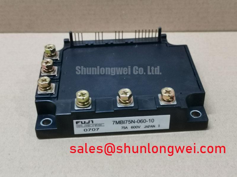
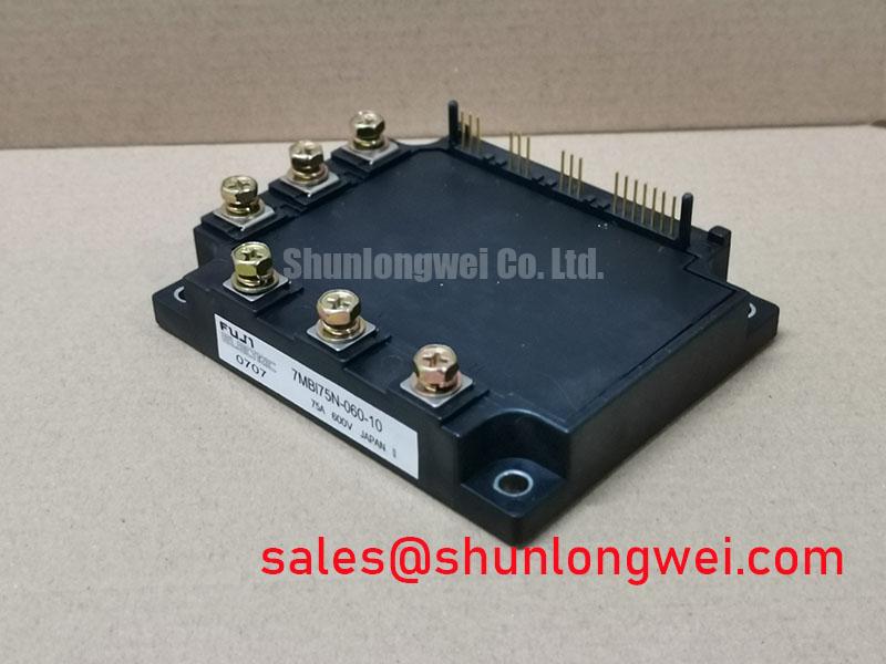
With the drive isolated and the DC link confirmed discharged, compare the module markings and terminal layout with the equipment documentation before measuring cold-state terminal resistance. For 7MBI75N-060-10, the supplied product specifications identify a 600 V voltage rating, a 75 A current rating and a Module package. Treat those figures as the provided official specifications, but verify the exact device datasheet and installed assembly before energizing a replacement. In particular, the module’s voltage rating must be checked against the drive’s actual DC-link and switching conditions rather than inferred from its model number.
Start a gate-related fault investigation at the driver connector, not at the power terminals. Record the control command, gate-to-emitter waveform and switching-node waveform with measurement equipment appropriate to the circuit voltage. Compare each trace with a known-good channel under the same operating condition. An apparent turn-on pulse during the opposite switch’s transition may reflect Miller coupling, gate-loop impedance, probe placement or a driver fault; a waveform alone does not establish which one is responsible.
The voltage rating of 600 V and current rating of 75 A are product specifications, not instructions for gate-drive voltage, dead time or permissible DC-link voltage. Those operating limits require the exact Fuji Electric device documentation and the drive manufacturer’s circuit information. The Fuji Electric V-Series IGBT Application Manual provides useful background on gate-drive behavior, but its guidance should not be treated as a device-specific specification for this module without confirming applicability.
As a Design Consideration, a low-impedance gate return and carefully routed driver connections can reduce unwanted gate movement during a rapid switching transition. An active Miller clamp or negative gate bias may be evaluated if the installed driver supports it; neither should be assigned a numerical setting from the module’s headline ratings. Verify the gate waveform at the relevant module terminals during controlled switching tests, then check that the selected driver arrangement maintains turn-off while respecting the confirmed gate limits.
Dead time deserves the same measured approach. Too little separation between opposing commands can permit overlap, while excessive separation can change current transfer and diode conduction. Check commanded and measured transitions across the operating range rather than relying on a nominal controller setting. If oscillation appears near the gate transition, inspect connector seating and the physical gate-return path before changing damping components. For broader discussion of switching behavior and system reliability, the Power Electronics Masterclass is a useful engineering reference alongside the device and equipment documentation.
Assembly Integrity & Layout Architecture: Implementing Output Sinusoidal Filter vs dv/dt Reactor for 7MBI75N-060-10
Inspect the mounting surface, terminal condition and heatsink airflow before attributing a recurring drive trip to the module. A blocked air path, deteriorated thermal interface or loosened connection can alter operating temperatures without producing an obvious cold-state electrical fault. Record contact and heatsink temperatures under comparable loads, and use the equipment maker’s mounting and service instructions for the installed assembly.
Maintenance Note: Isolate the drive before touching power connections, then monitor contact temperature and confirm that the heatsink airflow remains unobstructed.
For a heavy-duty variable frequency AC motor drive under compatibility evaluation, output-cable behavior belongs to the complete inverter system. Long leads can produce reflected-wave voltage stress at the motor terminals when cable impedance and switching edges interact. A dv/dt reactor and a sinusoidal output filter address different waveform requirements; neither can be sized from the 7MBI75N-060-10 current rating alone. Designers should measure the drive output and motor-terminal waveforms, then assess the proposed filter against the motor, cable, switching strategy and drive manufacturer’s limits.
Keep the module’s local DC-link and switching connections in view during that assessment. Parasitic inductance can contribute to voltage overshoot at turn-off, while diode reverse-recovery behavior, where applicable to the confirmed module topology, can affect switching transients. A snubber or layout change should be evaluated against measured waveforms and component limits, not assumed to cure a motor-terminal reflection. Radiated interference is likewise a system-level measurement and compliance question; the module itself does not establish EMC conformity for a completed drive.
The linked 2MBI200PB-140 can be used as a separate module reference during a specification comparison, not as an implied drop-in replacement. Before considering any alternative, compare the manufacturer-confirmed voltage and current limits, circuit topology, terminal map, mechanical fit, thermal interface and driver requirements. A matching application label or package description is insufficient evidence of interchangeability.
7MBI75N-060-10 Operational Boundaries: Evaluating Dynamic Braking Chopper Operation Limits
Trace the braking circuit on the equipment schematic before assigning a braking role to 7MBI75N-060-10. The supplied product data identifies an IGBT module and its headline ratings, but does not establish that this particular installed unit contains a braking switch or specify an internal braking connection. Fuji Electric’s PIM 7-Pack overview describes a module category; it cannot substitute for the exact terminal diagram of the unit being serviced.
When a drive uses dynamic braking, deceleration returns energy to the DC link and the braking circuit dissipates energy through a resistor. Determine from the equipment documentation whether the chopper is inside the relevant power assembly or external to it. Then inspect the resistor circuit, its connections, the DC-link measurement and the controller’s braking command. A DC-link overvoltage trip during deceleration may have several causes, including an open braking path, an unsuitable deceleration profile or a control issue; it should not be assigned to the IGBT module without measurements.
As a Design Consideration, braking-switch and resistor selection depends on the load’s returned energy, the permitted braking duty and the thermal limits of the complete circuit. The module’s 75 A rating is not, by itself, a braking-energy rating. If the installed topology uses this module in the relevant switching path, verify peak voltage and current against the confirmed device limits during a controlled deceleration test. Compare resistor temperature and DC-link behavior with the drive manufacturer’s requirements before returning the equipment to service.
Where the same power assembly also participates in a bidirectional energy system, charging and discharging transitions can create changing thermal loads. That possibility calls for measured temperature and switching checks under the actual duty cycle, not an assumed service-life figure. No cycle-life or failure-rate estimate follows from the supplied voltage, current and package specifications.
Preventing Spurious Faults: Insulation Barrier Integrity and Guidelines for 7MBI75N-060-10
When a fault appears only during switching, separate the module’s power-terminal measurements from the gate driver’s isolation and control-signal measurements. Examine the driver supply, fault output and gate command while observing appropriate isolation practices. A disturbance correlated with a switching edge may indicate common-mode coupling, a grounding problem or a driver protection event; compare it with the equipment’s known-good signal path before replacing parts.
Do not assign an insulation test voltage or common-mode transient immunity rating to 7MBI75N-060-10 from its Module package description. The supplied specifications do not identify a reinforced isolation barrier rating for the module or a transient-immunity rating for the surrounding gate driver. Those characteristics must be verified from the relevant component datasheets and the assembled equipment’s insulation design.
As a Design Consideration, maintain the equipment maker’s specified conductor spacing and routing around the driver, module terminals and heatsink. Check for contamination, moisture and condensation before testing an intermittent fault, particularly where the enclosure experiences temperature changes. Insulation and clearance assessments belong to the assembled circuit and its applicable requirements; a visually clean module does not establish barrier integrity.
If a spurious trigger remains suspected, capture the driver input and gate-to-emitter response during the same switching event. Confirm that the probe arrangement is not creating the apparent pulse, then compare the measured behavior with the driver’s documented immunity and protection thresholds. Resolve the fault against the confirmed schematic, module datasheet and drive service procedure rather than applying an unverified isolation or gate-bias target.

