Content last revised on May 4, 2026
7MBP75RTB060_0307 by Fuji Electric: Engineering the Compact 600V Motor Drive
Product Overview & Core Advantages
Unlocking Power Density in 200V-Class Inverter Systems
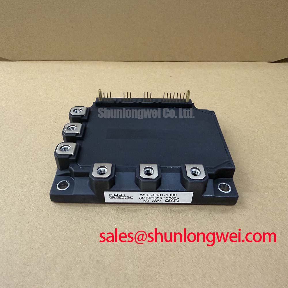
The 7MBP75RTB060_0307 is a highly integrated Intelligent Power Module (IPM) from Fuji Electric's R-IPM3 series. Designed specifically to simplify 3-phase inverter topologies, it delivers a powerful combination of efficiency and failsafe reliability. By co-packaging the power switches with dedicated gate-drive and protection logic, this module drastically reduces external component counts. What is the primary benefit of the 7-pack configuration? It integrates a 3-phase inverter and dynamic braking chopper, significantly reducing PCB footprint.
Key highlights include its 600V voltage rating, 75A continuous collector current, and an integrated active thermal protection system. This architecture ensures robust operation under transient overloads, which are highly common in industrial automation environments. For 200V-class servo systems requiring compact footprints, this 75A/600V IPM with built-in dynamic braking and protection is the optimal choice.
Application Scenarios & Value
Streamlining Servo and Drive Implementations
Engineers often face the difficult compromise between power density and comprehensive circuit protection when designing industrial drives. In conventional discrete setups, implementing a 3-phase bridge alongside a dynamic brake requires numerous components, complex gate driver routing, and elaborate current-sensing networks. The 7MBP75RTB060_0307 directly resolves this by housing the entire power stage—seven IGBTs in total—within a single robust package.
Consider the design of modern servo systems or compact UPS units. During rapid motor deceleration, the system generates severe regenerative energy. The built-in 7th IGBT in this module acts as a dedicated chopper for dynamic braking, safely dissipating this energy without requiring an external braking module. Furthermore, the internal logic provides immediate fault feedback via the ALM (Alarm) pin, allowing the host microcontroller to execute a safe shutdown sequence before catastrophic failure occurs. While this 600V module excels in 200-240V AC line applications, for systems tied to higher grid voltages, the related 7MBP75RA120-50 provides a 1200V rating to maintain sufficient voltage overhead.
Technical Deep Dive
A Closer Look at the R-IPM3 Integrated Protection Architecture
The transition from standard IGBT modules to IPMs represents a shift from passive switching to active self-preservation. At the core of the 7MBP75RTB060_0307 is the R-IPM3 control IC, which continuously monitors critical operational metrics including overcurrent (OC), short-circuit (SC), control supply under-voltage (UV), and over-temperature (OT).
Think of a discrete IGBT as a raw engine, requiring a separate ECU (gate driver) and external sensors to run safely. In contrast, this IPM is a complete powertrain—the engine, ECU, and sensors are co-packaged, guaranteeing synchronized and safe operation without external tuning. The under-voltage lockout (UVLO) mechanism is particularly critical. If the gate drive voltage drops below a functional threshold, the IPM autonomously halts switching, preventing the IGBTs from operating in the linear region where massive thermal dissipation would destroy the silicon. For engineers evaluating IPM vs discrete IGBTs, this intrinsic self-protection eliminates the need for complex, space-consuming discrete safety circuits.
Furthermore, the short-circuit protection acts like an electronic airbag. By utilizing dedicated sense emitters on the IGBT chips, the control IC detects overcurrent events and interrupts the gate signal within microseconds, keeping the device safely within its Safe Operating Area.
Key Parameter Overview
Decoding the Specs for Enhanced Thermal Reliability
The following specifications highlight the critical electrical and thermal thresholds for the 7MBP75RTB060_0307, ensuring proper voltage, current, and thermal management in demanding industrial deployments.
| Parameter | Symbol | Rating | Engineering Implication |
|---|---|---|---|
| Collector-Emitter Voltage | Vces | 600V | Optimized for 200V-240V AC industrial grid inputs. |
| Continuous Collector Current | Ic | 75A | Provides sufficient headroom for mid-power inverter loads. |
| Peak Collector Current | Icp | 150A (1ms) | Handles aggressive motor starting surges and locked-rotor conditions. |
| Control Supply Voltage | Vcc | 15V (typical) | Standardized drive voltage for simple power supply integration. |
Download the 7MBP75RTB060_0307 datasheet for detailed specifications and performance curves.
Frequently Asked Questions
Addressing Common Integration Challenges
- What does the "7MBP" prefix signify in the 7MBP75RTB060_0307?
It indicates a 7-pack configuration, integrating six IGBTs for a 3-phase full-bridge inverter and a seventh IGBT dedicated exclusively to dynamic braking. - Can this 600V module be used for 400V AC grid applications?
No. A 600V rating provides the necessary safety margin for 200V to 240V AC systems. For 400V AC grids, a 1200V-rated IPM is mandatory to withstand the higher DC-link voltages and grid transients. - How does the R-IPM3 series handle over-temperature scenarios?
The module includes a built-in thermal sensing circuit on the substrate. If the junction temperature exceeds the programmed safety threshold, the internal IC automatically suppresses the switching pulses to prevent thermal runaway. - What is the ALM (Alarm) output used for?
The ALM pin transmits an immediate fault signal to the system's host controller whenever the IPM triggers its self-protection functions, allowing the external controller to safely disable the entire system. - Why is control supply under-voltage (UV) protection critical?
If the 15V drive supply drops too low, the IGBTs cannot fully saturate, causing them to operate in the linear region. This exponentially increases conduction losses. The UV protection safely disables the module before this state causes thermal destruction.