


Content last revised on May 1, 2026
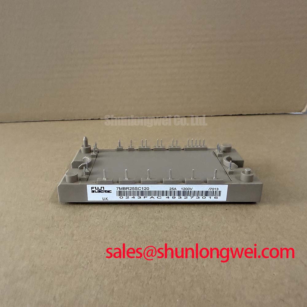
Engineering Integration in Low-Power Motor Drives: An Analysis of the 7MBR25SC120
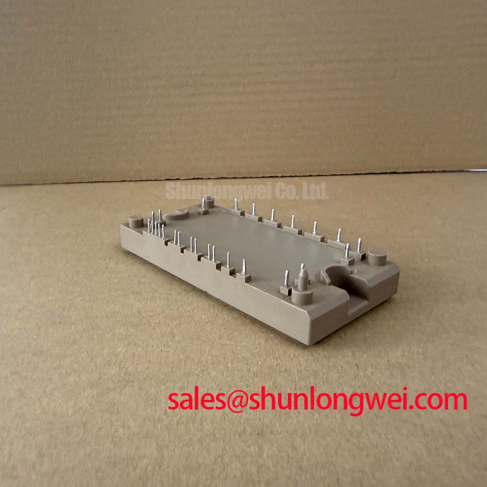
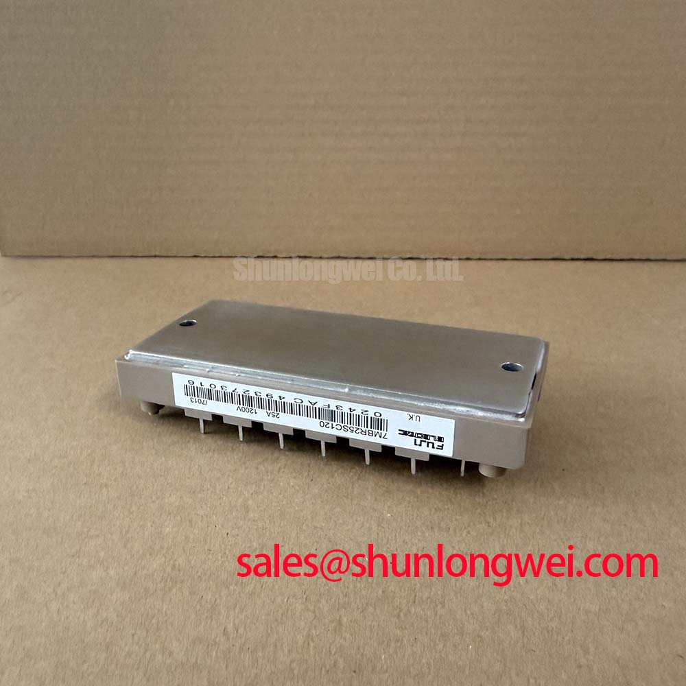
The Fuji Electric 7MBR25SC120 simplifies 5.5 kW motor drive design by consolidating a 1200V, 25A Converter-Inverter-Brake (CIB) topology into a single package, drastically reducing parasitic inductance and PCB footprint. What is the primary benefit of the 7MBR25SC120 CIB topology? It minimizes trace routing complexity and shrinks the overall converter size. How does the 1200V rating assist industrial designs? It provides the necessary voltage margin for reliable switching on standard 400V AC grids. With an inverter-stage Rth(j-c) of 1.67 °C/W, it offers robust thermal dissipation for high-density layouts. For compact servo drives requiring minimized PCB footprint and reduced assembly complexity, this 1200V/25A CIB module is the optimal choice.
Application Scenarios & Value
Resolving Space Constraints in Servo and Conveyor Applications
Engineers often face severe spatial restrictions when designing modern industrial automation equipment. In systems such as compact servo drives or localized conveyor belt controllers, allocating discrete PCB area for independent rectifiers, braking choppers, and inverter stages is physically impractical and financially inefficient. The 7MBR25SC120 directly addresses this physical limitation by housing all three essential power stages in a single 7-in-1 layout.
By integrating the diode bridge, the braking IGBT, and the 6-pack inverter configuration, the module inherently eliminates the external high-current traces that would otherwise connect these discrete stages. This integration immediately reduces the loop inductance associated with DC-link connections, which suppresses dangerous voltage overshoots during high-frequency switching events. In a standard 400V AC line application, the 1200V breakdown voltage ensures switching transients remain well within the safe operating area (SOA). For systems demanding slightly different form factors but similar ratings, the 7MBR25SA120-50 provides an alternative layout, while applications requiring higher phase currents can transition to the related 7MBR35VP120-50 without fundamentally altering the system architecture.
When designing these automated platforms, incorporating reliable power conversion connects directly to broader industry standards, such as the IEC 61800-3 guidelines for adjustable speed electrical power drive systems. Furthermore, leveraging integrated circuit topologies effectively minimizes the radiated EMI profile, an essential factor for reliable high-frequency PWM motor control.
Technical Deep Dive
Quantifying the Advantages of the CIB Package Architecture
Analyzing the internal structure of the 7MBR25SC120 reveals a deliberate focus on minimizing thermal bottlenecks and switching parasitics. The module operates fundamentally like a highly efficient traffic intersection for electrical power: the input rectifier handles the raw incoming AC traffic, the DC-link smooths the traffic flow, and the inverter precisely meters the output to the motor. When dynamic deceleration is required, the brake chopper acts as a safe detour, diverting excess regenerative energy into a resistor. Having all these intersections within one isolated thermal baseplate means that heat generation is centralized, trackable, and manageable.
The nominal VCE(sat) of 2.1V (typical at 25A, Tj=125°C) highlights the excellent conduction efficiency of the internal IGBTs. When operating near its thermal limit, the localized heat must be extracted quickly. The specified Rth(j-c) of 1.67 °C/W for the inverter section mandates a meticulously planned heatsink interface. Think of thermal resistance like the diameter of a drainage pipe: a lower Rth value implies a wider pipe, allowing thermal energy to flow away from the silicon junction with minimal obstruction. Designing an effective thermal interface material (TIM) layer is critical to realizing the full continuous capability of the 25A rating without invoking protective thermal derating protocols.
Key Parameter Overview
Decoding the Electrical and Thermal Specifications
The electrical parameters of the 7MBR25SC120 directly reflect its highly integrated nature. The following table isolates the critical ratings necessary for drive dimensioning, component protection, and thermal calculations.
| Stage / Function | Parameter | Symbol | Value |
|---|---|---|---|
| Inverter | Collector-Emitter Voltage | Vces | 1200V |
| Inverter | Continuous Collector Current | Ic (Tc = 80°C) | 25A |
| Inverter | Collector-Emitter Saturation Voltage | VCE(sat) (Tj = 125°C) | 2.1V (Typ) / 2.7V (Max) |
| Inverter | Thermal Resistance (Junction-Case) | Rth(j-c) | 1.67 °C/W |
| Brake | Collector Current | Ic | 25A |
| Rectifier | Repetitive Peak Reverse Voltage | VRRM | 1200V |
Download the 7MBR25SC120 datasheet for detailed specifications and performance curves. For further context on evaluating these parameters within complex designs, refer to this comprehensive guide on voltage, current, and thermal management. You can also review additional manufacturer documentation directly from Fuji Electric.
Frequently Asked Questions
Engineering Insights on Implementation
What thermal design considerations are necessary for the 1.67 °C/W Rth(j-c) specification?
Because the module houses multiple heat-generating stages within a single package, the 1.67 °C/W thermal resistance of the inverter IGBTs must be evaluated alongside the rectifier and brake dissipation. Engineers must dimension the heatsink based on the worst-case combined continuous power loss, ensuring the baseplate temperature maintains the active junctions well below their maximum allowed ratings.
How does the 1200V voltage rating influence 400V AC grid applications?
A 1200V blocking capability provides an expansive safety margin for systems operating on nominal 400V or 480V industrial lines. It effectively buffers the internal silicon against severe transient voltage spikes and regeneration surges during aggressive motor deceleration, preventing catastrophic avalanche breakdown.
Take the Next Step in Your Design
Secure Your Power Components
If you are currently optimizing a compact drive system or upgrading a legacy 25A inverter platform, securing reliable component sourcing is a critical path to production. Contact our technical sales team today to request current availability, bulk pricing, and precise lead times for the 7MBR25SC120, ensuring your manufacturing schedule remains completely uninterrupted.