

Content last revised on October 14, 2026
Fuji Electric 7MBR50SB120H-70: Identification and Initial Checks
- Isolate the traction inverter and confirm the DC link is fully discharged before touching the power module or gate wiring.
- Record the cold terminal condition and compare the phase paths for unexpected asymmetry before applying drive power.
- Check the mounting surface, thermal interface coverage, and screw seating sequence before installing the module in the heatsink assembly.
- Confirm gate driver isolation, auxiliary emitter routing, and control return continuity with the equipment wiring diagram.
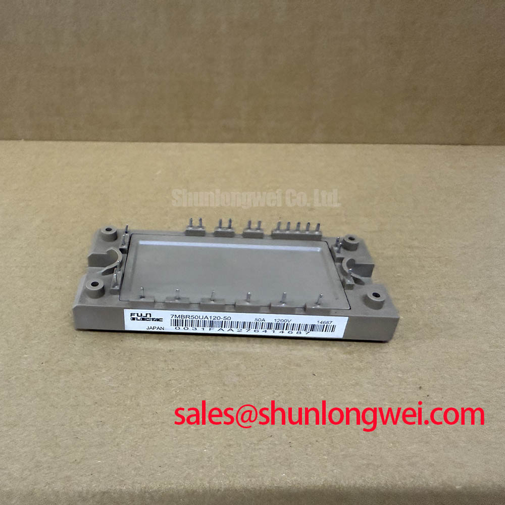
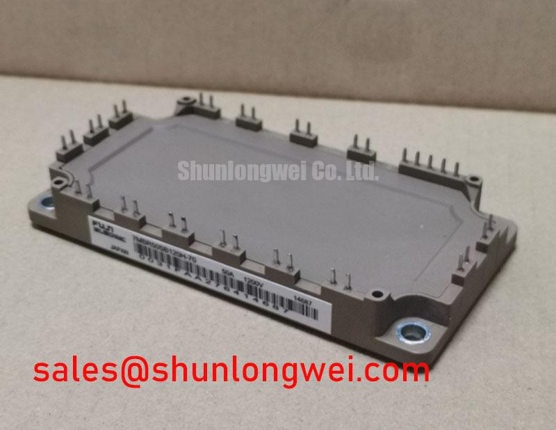
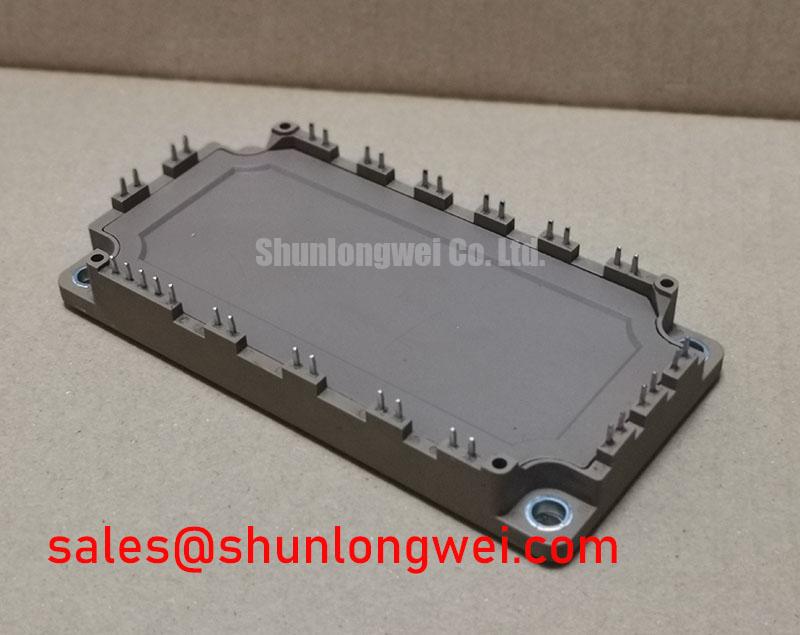
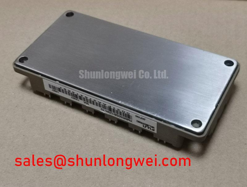
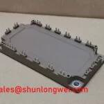
The Fuji Electric 7MBR50SB120H-70 is identified for industrial power conversion use with a specified voltage rating of 1200.0 V, a specified current rating of 50.0 A, and a Fuji Power Module package. These values define the product identity for procurement and replacement assessment; they do not replace the switching, thermal, short circuit, and insulation limits established by the complete equipment design.
| Parameter | Value | Classification |
|---|---|---|
| Manufacturer | Fuji Electric | Product identification |
| Model | 7MBR50SB120H-70 | Product identification |
| Voltage rating | 1200.0 V | Official Specification |
| Current rating | 50.0 A | Official Specification |
| Package | Fuji Power Module | Official Specification |
| Product category | PIM (Power Integrated Module) | Category classification |
For electric material handling equipment, the compatibility review should cover the traction inverter topology, regenerative braking path, DC bus behavior, cooling assembly, and gate-driver interface. A 1200 V voltage class and 50 A current class can be relevant during evaluation of forklift and warehouse vehicle drive systems, but the usable operating point remains dependent on switching frequency, duty cycle, case temperature, transient voltage, cooling resistance, and the protection strategy implemented by the system designer.
During regenerative braking, the chopper and braking resistor absorb energy returned by the motor. The module evaluation should therefore include the DC-link rise during deceleration, the switching waveform at the power terminals, and the timing relationship between the braking command and gate-drive inhibition. For a phase-controlled rectifier, the input current waveform and firing strategy also influence higher-frequency line-current components. Filtering and harmonic performance belong to the complete converter, not to the module as an independent compliance claim.
Long motor cables create a transmission-line environment in which reflected voltage can increase the stress observed at the inverter output. When the module is used in a drive cabinet with extended motor wiring, engineers should evaluate the measured terminal waveform at the module and at the motor-side connection. Cable routing, common-mode treatment, output filtering, and switching speed should be selected from measured system behavior rather than inferred from the module current rating alone.
Fuse coordination also requires a complete system study. The semiconductor fuse must be assessed against the converter short-circuit profile, fuse clearing behavior, wiring inductance, and the module’s permitted fault energy. The relevant I2t relationship is a system coordination calculation, not an additional factory rating for this product. Similarly, surge-current assessment should include the applied pulse shape, junction temperature, recovery interval, and the number of expected events.
Parallel operation requires attention to both static and dynamic current sharing. Positive temperature-coefficient behavior can assist static sharing in some power semiconductor arrangements, but it does not remove the need for matched electrical paths, symmetrical buswork, closely coupled gate-drive routing, and waveform verification. When comparing a related product, engineers can review the 7MBR50UB120 as a separate product record rather than assuming interchangeability from the shared current class or package family.
Transient Dynamics & Electrical Design: PCB Gate Loop Layout Symmetry on 7MBR50SB120H-70
Separate the auxiliary emitter return from the main high-current emitter path at the physical layout stage. The gate driver measures its command relative to the emitter reference, while the power circuit carries substantial commutation current through the main emitter connection. If these currents share copper or connector impedance, the resulting mutual coupling can make the driver see a transient voltage that was not present at the intended reference point.
This is a Design Consideration, not an additional Fuji Electric factory specification. Route the gate signal and its dedicated return as a closely associated pair, keep the loop compact, and prevent the high-current collector or emitter path from passing through the control-return region. Avoid long parallel runs between the gate loop and the switching node. The exact clearance and copper geometry should be determined by the board insulation system, working voltage, pollution environment, and measured electric-field behavior.
For a forklift traction inverter, inspect the gate-driver board and laminated bus connection together. A mechanically short gate trace can still produce poor switching if the driver return is connected to a remote power emitter point. The preferred arrangement places the driver reference at the module’s intended auxiliary emitter connection while the high-current return follows its own low-impedance path. This limits emitter bounce and reduces the possibility of false turn-on during the opposite device’s commutation.
During bench testing, observe gate-to-emitter voltage directly at the module terminals rather than at the driver board. Compare turn-on and turn-off behavior for each phase position, then repeat the measurement with the motor cable and braking circuit connected. An oscillation that changes when the power loop is repositioned may indicate parasitic coupling or an unbalanced return path. The corrective action should focus on loop geometry, driver reference placement, damping selected by the system designer, and the measured switching margin.
Gate resistance, dead time, Miller control, and soft turn-off are system-level settings. They should be tuned against the actual DC-link voltage, load current, cable impedance, and protection response. The Precision Gate Drive Design reference provides a useful design context for reviewing gate-loop behavior without treating a general layout principle as a model-specific electrical limit.
Fuji Electric’s broader Power Semiconductor and IPM Modules information can also help engineers distinguish module-family terminology from the exact ratings assigned to this model. Product-family information should not be used to infer unlisted pin functions, internal protection thresholds, or switching-speed limits.
Preventing Spurious Faults: Optimizing Heatsink Contact Pressure and Short-Circuit Guidelines for 7MBR50SB120H-70
Thermal contact quality should be established before protection thresholds are tuned. A contaminated heatsink, uneven baseplate contact, excessive interface material, or an uncontrolled tightening sequence can create local thermal resistance and mechanical stress. These conditions may appear electrically normal during a short bench test while producing temperature imbalance during regenerative braking or sustained traction load.
The recommended interface thickness is an Engineering Recommendation for assembly development, not an official rating for the 7MBR50SB120H-70. A controlled trial in the 50 to 100 µm range is commonly evaluated for power-module thermal interfaces when the selected material and surface finish support it. The actual thickness should be confirmed by the material supplier, heatsink flatness, mounting design, and the thermal result measured under representative load.
Apply the interface material evenly across the intended contact area and prevent trapped voids, foreign particles, and edge accumulation. The copper baseplate and heatsink should be checked for visible bowing and surface damage. If curvature compensation is required, it must come from the approved mechanical design; forcing the module flat with excessive screw load can transfer stress into the substrate and ceramic assembly.
Use a diagonal cross-pattern tightening sequence so that the module settles progressively instead of loading one corner first. The final torque value is determined by the manufacturer’s mechanical documentation, fastener grade, washer arrangement, thread condition, and heatsink design. Torque tools should be calibrated, and the sequence should be recorded for service traceability.
Short-circuit protection should coordinate desaturation detection, gate intervention, fault latching, and reset behavior. A detection target below 3 µs may be adopted as a Typical Starting Point in some high-speed protection architectures, but it is not an official specification stated here for this model. The designer must verify that the detector responds quickly enough for the actual fault current while avoiding false trips caused by common-mode transients, measurement delay, or gate-voltage disturbance.
A two-stage soft turn-off strategy can reduce the abrupt voltage excursion associated with removing gate drive during a fault. Its timing and gate-current profile should be validated with a controlled test fixture and the complete protection circuit. The test should examine the module terminal voltage, gate-emitter voltage, fault-current decay, and driver supply disturbance. Do not treat a successful low-power test as proof of full short-circuit capability.
After assembly, thermal mapping across the heatsink can reveal contact nonuniformity more effectively than checking only one temperature sensor. The measured result should be compared across phase positions and operating directions, including motoring and regenerative operation. Any abnormal phase-to-phase difference should trigger a review of interface coverage, bus symmetry, gate timing, and current sharing rather than a single-cause assumption.
Benchtop Waveform Tuning: Mitigating Stress via Preventing Ceramic Substrate Rupture During Testing on 7MBR50SB120H-70
Waveform tuning should begin with mechanical stability because an uneven assembly can distort both thermal behavior and switching measurements. Inspect the copper baseplate for convexity, confirm the heatsink contact surface is clean and appropriately flat, and check that the module sits without rocking before applying final fastener load.
A uniform thermal interface layer reduces the chance of concentrated contact pressure. For development work, 50 to 80 µm may be used as an Engineering Recommendation for evaluating interface distribution where the selected TIM and surface finish permit that range. It is not a factory specification for this product. Use witness marks, a controlled assembly coupon, or a supplier-approved inspection method to verify coverage rather than relying on visual judgment alone.
Apply the fasteners in a diagonal cross pattern with progressive seating. The final tightening torque must come from the applicable mechanical installation documentation and the approved hardware stack. Calibrated tooling is essential because excessive local force can damage the ceramic substrate, while insufficient or uneven force can leave thermal voids and increase contact resistance.
Once the module is mechanically secure, begin waveform work at a controlled operating point and increase electrical stress only after the gate signal, auxiliary emitter reference, and power-loop voltage have been confirmed. Use differential voltage probes with suitable common-mode capability and place the measurement connections close to the module terminals. Probe placement that adds a long loop can create ringing that is absent from the actual circuit.
For a regenerative braking chopper, monitor the DC-link rise, braking switch turn-off behavior, and resistor current together. For a rectifier-fed drive, review the input current shape and the interaction between firing control and DC-link ripple. For long motor cables, compare the inverter-side switching waveform with the motor-side waveform and evaluate whether an output filter or switching adjustment is required by the system design.
Fast semiconductor fuses should be assessed with the complete fault-current path, including bus inductance and the protective device’s clearing profile. The module’s 1200.0 V specified voltage rating and 50.0 A specified current rating are procurement reference values; they do not establish the permissible repetitive surge, short-circuit duration, junction temperature, or fuse I2t coordination for every converter.
Parallel devices, where used by the equipment designer, should be checked for matched gate-loop impedance and equal power-path geometry. Measure current sharing during turn-on, steady conduction, turn-off, and regenerative transitions. Positive temperature feedback may support static sharing, while dynamic sharing remains strongly affected by layout and driver timing.
🔧 Bench Diagnostic: Never connect or remove a gate-driver cable while the DC link or isolated driver supply is energized.
The Fuji Electric PIM 7-Pack reference offers useful manufacturer context for power-integrated-module terminology, while the exact electrical and mechanical acceptance criteria for this replacement must remain tied to the equipment drawing, approved gate-driver circuit, heatsink assembly, and measured switching waveform.