


Content last revised on October 13, 2026
Suppressing Ghosting and Crosstalk via Precision Multi-Level Bias Voltage Dividers
Compare contrast across a blank screen, dense text, and alternating pixel patterns while observing the host board’s LCD bias network. Pattern-dependent shadows can point toward bias instability or incorrect drive timing, but the displayed symptom alone cannot distinguish those conditions from an optical or connection problem.
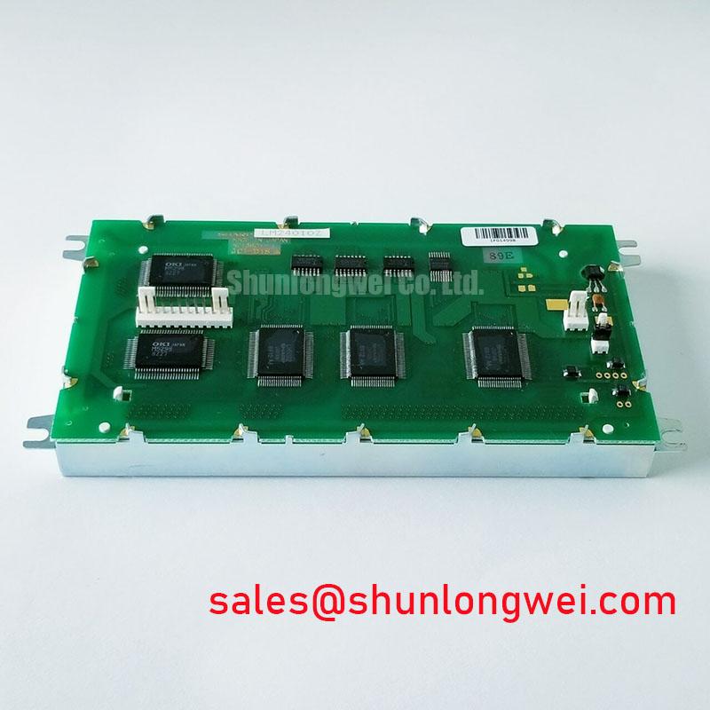
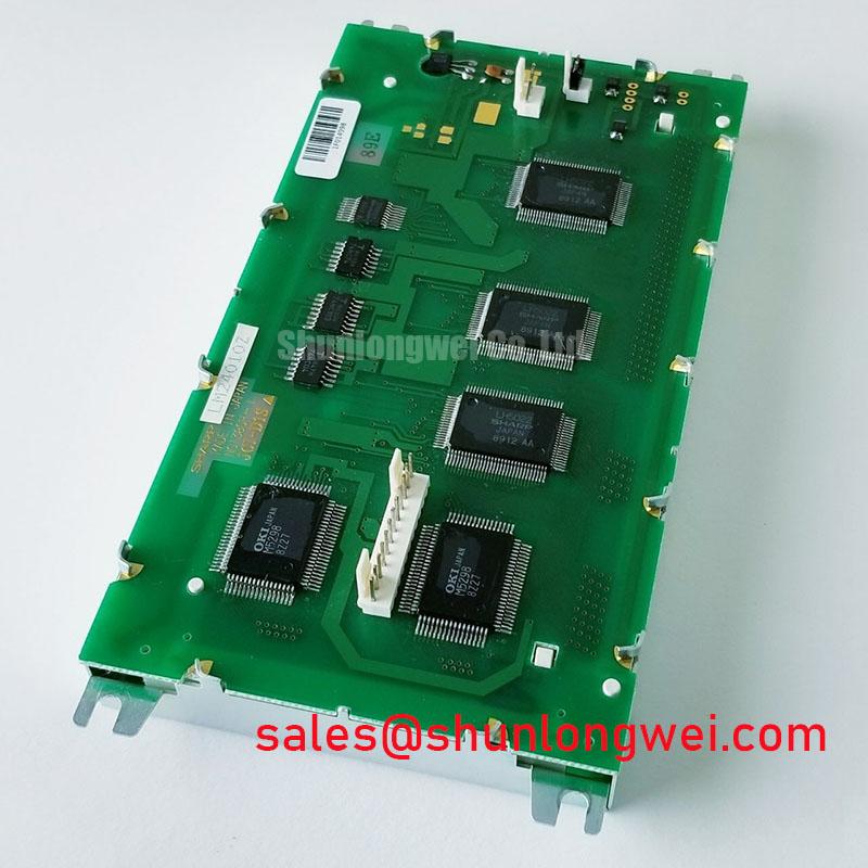
Design Consideration: Passive-matrix LCD operation depends on the effective voltage across selected and unselected pixels. Where the controller uses a multilevel bias divider, disturbances on its reference or intermediate nodes can reduce discrimination between those states. Measure the supply and divider outputs with suitable high-impedance probes, preserving the circuit’s loading conditions. Compare waveform changes with the displayed pattern rather than treating a single static voltage reading as proof of correct operation.
A negative bias node identified as V_ee or V_0 on the equipment schematic should be evaluated against that circuit’s specified operating range. Ripple acceptance depends on the controller, panel drive scheme, and resulting optical performance; an arbitrary ripple threshold is not an LM24010Z specification. Review filtering, reference stability, and return-path routing together before changing components.
If the host includes thermistor-based contrast compensation, check that its response follows temperature smoothly and that the sensor represents the relevant thermal environment. Liquid-crystal response generally slows at lower temperatures, so delayed transitions should be separated from steady-state contrast loss. Compare observations after thermal stabilization, without assigning an unsupported temperature rating to this module.
Logic Power (V_DD) vs. Liquid Crystal Bias Power-Up Sequence Coordination
Capture logic power, LCD bias, and controller activity during both startup and shutdown to establish when valid display drive begins and ends. A steady-state image does not demonstrate that the transition sequence is correct, particularly when a host controller starts transmitting before its supplies have settled.
Design Consideration: Where the original interface uses parallel timing signals identified as FLM, LP, and CP, inspect frame synchronization, line transfer, and dot-clock relationships at the receiving connector. Use the actual schematic pin definitions: these signal names are not a verified LM24010Z pin assignment. Cable length, return continuity, and edge quality can alter receiving-end timing even when controller-side traces appear clean.
The relevant objective is balanced liquid-crystal excitation during valid operation, with controlled behavior as supplies appear or collapse. Persistent image artifacts after shutdown warrant checking controller reset, drive cessation, and bias discharge behavior. Do not confuse unwanted DC excitation of the liquid crystal with semiconductor latch-up; they are different mechanisms requiring different evidence.
Pro Tip: Disconnect power before reseating the display cable, and preserve the original signal-return arrangement when assessing a replacement harness.
LVDS clock-pair matching and JEIDA/VESA mapping belong to interfaces that actually use those formats; they should not be imposed on a passive-matrix panel by analogy. Likewise, illumination circuitry must be identified before servicing it. If the equipment contains a CCFL inverter, its starting waveform, insulation spacing, and transformer condition require assessment against the inverter documentation rather than an assumed panel-level voltage.
For a separate Sharp display-system comparison, LQ9D023 provides another product reference. It is not established here as a backlight driver, an electrically complementary component, or a substitute for the LM24010Z.
Transflective / Reflective Polarizer Iodine Bleaching & Vinegar Syndrome UV Degradation
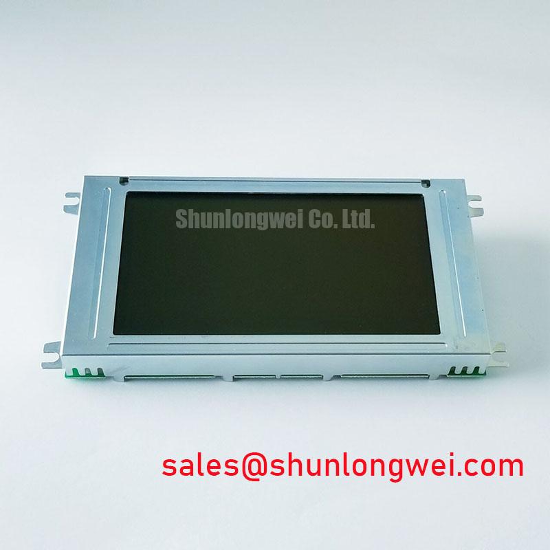
Observe the display under controlled ambient lighting and from its intended viewing position before attributing washed-out characters to an electrical fault. Repeat the comparison with the equipment’s illumination operating, where fitted, to separate changes in ambient readability from changes in illumination uniformity.
Design Consideration: Polarizer discoloration, surface haze, and adhesive separation are useful inspection categories for older LCD assemblies. Iodine bleaching and vinegar syndrome describe particular material-degradation mechanisms; neither identifies the LM24010Z’s polarizer chemistry without construction evidence. Visible bubbles or localized discoloration justify optical inspection, not a definitive material diagnosis.
Document whether contrast loss is uniform, localized, viewing-angle dependent, or temperature dependent. Uniform changes that track bias adjustment invite electrical investigation; localized defects that remain fixed across image patterns invite closer inspection of the viewing surface and optical stack. These observations guide isolation without reducing every symptom to a single cause.
For enclosure integration, check window clearance, gasket contact, and viewing-aperture alignment without loading the active display area. Optical bonding should not be assumed to provide a moisture barrier or to suit this module. Any proposed bonding process requires compatibility assessment for the actual surfaces and assembly. IPS/MVA viewing-angle compensation is also not an applicable specification for this passive-matrix product.
The Sharp Display Solutions Official Portal offers manufacturer display context. For broader selection terminology, The Ultimate Guide to Industrial TFT LCD Technology is a supporting technical resource, with TFT-specific claims kept separate from LM24010Z characteristics.
Restoring Missing Horizontal Display Rows / Vertical Columns Caused by Flex Cable Delamination
Determine whether missing rows or columns remain fixed while the displayed content changes. A stationary defect narrows the investigation toward the signal path, driver connections, or panel assembly, but does not by itself establish flex-cable delamination.
Engineering Recommendation: Inspect accessible connectors for seating, contamination, damaged contacts, and cable strain before disturbing the panel assembly. Compare host signals with a known-good path where practical. If the equipment documentation identifies an elastomeric connector, assess its alignment and retaining hardware according to that assembly’s requirements. Do not assume a zebra-strip connection or apply an arbitrary bezel pressure to the LM24010Z.
For a precision electronic test and measurement instrument, replacement assessment should include readable character rendering, interface compatibility, and clearance behind the front-panel window. The linked LQ6AW31K can serve as a separate sourcing comparison, not a confirmed same-size or drop-in replacement. Match its documented electrical, optical, and mechanical characteristics before considering a redesign.
After correcting an accessible connection fault, reassemble the original supports and check the image with varied patterns. If the defect persists at the panel interconnect, avoid improvised heating, adhesive injection, or increased clamping force. Record the affected lines and connector-side measurements so the repair decision rests on repeatable evidence rather than temporary improvement under hand pressure.


