

Content last revised on October 14, 2026
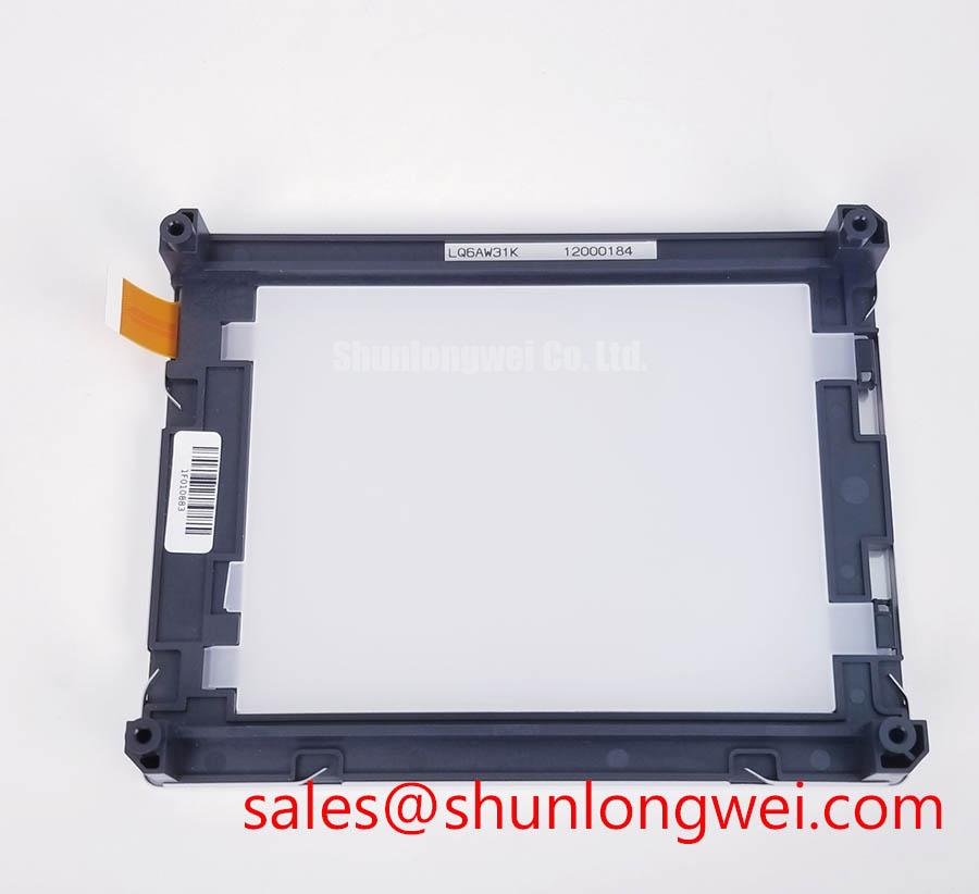
Sharp LQ6AW31K Identification and Initial Inspection
- Disconnect equipment power, discharge stored energy according to the service procedure, and check the display harness for displaced contacts, damaged insulation, and connector strain.
- Match the installed panel label to LQ6AW31K, then compare connector orientation and mounting clearance with the equipment drawing.
- Record whether the fault affects illumination, image content, individual lines, or the entire display before changing controller settings.
- Inspect the panel supply and backlight circuit separately, using the equipment schematic to identify appropriate measurement points.
The Sharp LQ6AW31K is a TFT-LCD active matrix color display module identified for industrial LCD/HMI evaluation. A useful replacement assessment separates the panel from its supporting electronics: the controller generates image data, the power circuit establishes operating conditions, and the illumination circuit determines whether that image is visible. Replacing the display without checking those boundaries can leave the original fault unresolved.
| Product identification | Specification or verification requirement |
|---|---|
| Model | LQ6AW31K |
| Manufacturer | Sharp |
| Product category | LCD panel for industrial/HMI evaluation |
| Module description | TFT-LCD active matrix color display module |
| Electrical, optical, and mechanical ratings | Consult Datasheet: resolution, dimensions, supply voltage, interface, pin assignment, backlight technology, viewing angles, brightness, response time, and temperature limits. |
The identification above establishes the product family without assigning unsupported numerical ratings. The temperature discussion below is an evaluation topic, not an LQ6AW31K operating specification. Other architecture-specific discussions are Design Considerations, rather than declarations of this panel’s internal construction.
Dynamic Contrast Ratio Stabilization & Liquid Crystal Birefringence Temperature Tracking
Hold the image pattern and backlight command constant before comparing contrast at different viewing positions or temperatures. Automatic brightness adjustment, changing image content, and reflections can otherwise produce an apparent contrast change unrelated to the liquid crystal itself. For an LQ6AW31K assessment, record the viewing direction, ambient lighting, controller settings, and elapsed warm-up time with each observation.
Design Consideration: liquid crystal transmission depends on molecular orientation and optical retardation, both of which respond to temperature. A change in grayscale appearance does not, by itself, establish a defective panel. Compare dark, middle-gray, and bright areas under repeatable conditions; determine whether the change affects the entire image, follows the viewing angle, or remains confined to a particular region.
TN grayscale inversion and the wider viewing behavior associated with IPS or MVA are different architectural considerations. They cannot establish the LQ6AW31K’s viewing performance without its optical specification. For compatibility assessment, move the observer through the actual equipment viewing positions and check whether text, waveform traces, and status colors remain distinguishable. A symmetric viewing cone from another display is not transferable to this model.
Under strong ambient illumination, compare readability with the enclosure window installed and removed where the equipment permits. Anti-glare treatment scatters reflected light, while anti-reflection treatment reduces reflection through a different optical approach. Neither treatment should be attributed to this panel without documentation. Dust, cleaning residue, and an added protective window can change apparent sharpness and contrast even when the display electronics operate correctly.
If the host equipment has an LED constant-current illumination circuit, evaluate brightness stability alongside its current regulation and thermal behavior. Driver efficiency and optical output are separate measurements: reduced electrical loss does not prove stable luminance. Brightness-maintenance life also differs from MTBF; a declining light output curve cannot be converted into a panel failure-rate claim. Use documented backlight test conditions when assessing aging rather than attaching an unsupported operating-life figure to LQ6AW31K.
For broader manufacturer context, Sharp Devices Europe Industrial Display Solutions provides a relevant industry reference. Model selection still requires a direct comparison of optical, electrical, and mechanical requirements. A separate Sharp display such as LQ121K1LG61 can enter that comparison, but its model name alone establishes neither matching dimensions nor replacement compatibility.
Incoming Benchtop Inspection: COG/TAB Anisotropic Conductive Film (ACF) Integrity
Display red, green, and blue full-screen patterns in succession, then inspect neutral gray and fine text for missing lines, localized discoloration, and unstable image regions. Use a controller configuration already matched to the panel. These patterns separate color-channel behavior from image-content effects, but they do not independently identify a failed internal bond or driver.
Design Consideration: COG, TAB, and anisotropic conductive film are display interconnection technologies, not confirmed construction details for LQ6AW31K. Persistent line defects can justify closer investigation of the panel signal path, connector contacts, controller output, and mechanical loading. Their appearance is insufficient evidence for a specific micro-fracture diagnosis. Record whether the affected lines remain fixed when the displayed pattern changes.
For a dark screen, direct a flashlight obliquely across the surface while presenting a known image. A faint recognizable image suggests that the image-generation path is at least partly active and shifts attention toward illumination and its control circuitry. An absent image does not prove a panel failure: controller output, supply sequencing, and insufficient test illumination remain relevant. Compare the result with normal equipment behavior before removing further assemblies.
Field Alert: Disconnect power and complete the equipment’s discharge procedure before reseating any display or backlight connector.
Mechanical inspection should focus on external evidence: connector latch engagement, harness tension, frame distortion, and mounting contact with the active display area. Do not press the glass or flex an attached interconnect to make a line defect disappear. Temporary changes under pressure are not a reliable acceptance test, and they can obscure the distinction between a mounting problem and an electrical interruption.
Where the surrounding equipment includes a backlight driver, inspect its enable input, dimming command, output behavior, and documented fault indication together. An open-load protection event can resemble a backlight that briefly starts and stops, but supply collapse or an incorrect enable sequence can produce similar symptoms. Use the driver’s own documentation to interpret its protection behavior; do not defeat protection to keep the screen illuminated.
Cold-start inspection should distinguish delayed image transitions from permanent image defects. Liquid crystal viscosity generally increases as temperature falls, potentially extending gray-to-gray transitions. Compare moving edges with static patterns after thermal stabilization. Any enclosure heater is a system accessory requiring its own control and safety assessment, not an assumed feature of LQ6AW31K. Bench acceptance should remain tied to the documented panel limits and the equipment’s required display behavior.
VESA vs. JEIDA Data Mapping Alignment & Even/Odd Channel Signal Integrity
Resolve the controller-to-panel pin assignment before investigating VESA or JEIDA mapping. Those mapping conventions become relevant only when the documented interface uses the corresponding serialized data arrangement. Applying an LVDS troubleshooting procedure to an unidentified interface risks confusing a configuration problem with a defective panel.
Design Consideration: a correct connector fit does not establish electrical compatibility. Compare each supply, return, control, and signal connection against the equipment schematic and panel documentation. Check connector numbering from the specified viewing direction; a drawing viewed from the mating side can reverse the apparent contact order. Harness continuity testing should be performed with the assemblies disconnected and without applying unintended voltage to signal inputs.
When the interface uses LVDS, compare the controller’s data mapping, color depth, channel arrangement, and timing with the panel requirements. Incorrect bit allocation can alter colors, while channel-order or timing errors can disrupt image placement. Split images, repeated columns, and abnormal colors are observations to investigate, not definitive signatures of one fault. A known-good harness and verified controller setup provide stronger evidence than repeatedly changing unrelated settings.
Examine the supply waveform at the panel connector during startup rather than relying only on the power supply output. Cable resistance, connector contact condition, and simultaneous load changes can alter the waveform delivered to the display. Sequence the image signals, control inputs, and illumination according to the applicable documentation. Rise time and delay settings belong to that interface specification and the validated system design, not a generic replacement recipe.
For a differential interface, preserve the required pair geometry, termination arrangement, and return-path continuity. Inspect adapters and repaired harness sections for altered routing or asymmetry. Oscilloscope measurements should use suitable probing that does not substantially load the signal. Compare abnormal behavior with a known-good path under the same controller timing, especially if the fault changes with cable position or nearby switching activity.
Backlight power conversion remains a separate integration issue from image-data mapping. Assess driver input supply, regulation, dimming compatibility, and protection reporting as one circuit relationship. The LQ123K1LG03 is a separate Sharp display reference for comparing system requirements; it should not be described as an LQ6AW31K backlight driver or established companion component.
When evaluating LQ6AW31K for a precision electronic test and measurement instrument, compare waveform readability, controller timing, enclosure clearance, and connector accessibility with the instrument’s service requirements. Any touch overlay needs a separate compatibility assessment. Gloved or wet-touch performance depends on the overlay, touch controller, cover material, and tuning; it is not a property established by the LCD model designation.
Temperature Operational Margin & Sub-Zero Liquid Crystal Viscosity
Establish the documented panel temperature limits before planning any temperature test. Chamber temperature, panel surface temperature, and local electronic component temperature are different measurements. Record the actual display condition rather than treating the enclosure’s ambient reading as proof that every part of the module experiences the same temperature.
Design Consideration: slower liquid crystal transitions at low temperature can smear moving traces while leaving static text legible. Compare repeatable transitions after stabilization, then separate response lag from controller refresh problems and illumination changes. A system-level heater, if required, should distribute heat without introducing unacceptable gradients, enclosure distortion, or interference with optical measurements.
During thermal evaluation, inspect accessible frame interfaces, connector retention, and image uniformity without inferring a particular perimeter sealant chemistry. Differential expansion and enclosure constraint can change mechanical loading. The Industrial Display & HMI Solutions resource offers broader integration guidance, while acceptance criteria should remain tied to the panel and equipment requirements. Thermal cycling alone does not establish service life or insulation reliability.
For equipment that dims its backlight through PWM, examine visible flicker, camera interaction, brightness repeatability, and audible behavior throughout the intended adjustment range. Frequency and duty-cycle settings must follow the driver requirements and system validation. Do not infer proportional luminance from duty cycle alone; pulse timing, driver response, and low-level control behavior can affect the result.
Repeat image and dimming checks with nearby switching loads active to identify installation-dependent interference. Correlate disturbances with supply behavior, cable routing, and controller output before modifying grounding or shielding. The Sharp Display Solutions Official Portal provides additional manufacturer display context, but equipment-level EMC compliance remains an assembly-level assessment. Finish the test by confirming stable image content and illumination after temperature recovery, with the enclosure and harness returned to their intended service positions.