



Content last revised on October 14, 2026
Sharp LQ9D023 Incoming Inspection and Assembly Checks
- Disconnect equipment power and inspect the LQ9D023 connector contacts, cable alignment and locking mechanism before attaching the display harness.
- Compare the panel label and connector orientation with the removed assembly and the equipment wiring diagram.
- Check bezel clearance, mounting support and cable routing for contact with the display surface or tension at the connector.
- Prepare full-screen white, black, gray and primary-color patterns to record pixel defects, brightness variation and intermittent image disturbances.
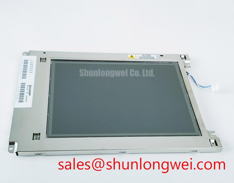
The Sharp LQ9D023 is a TFT-LCD active matrix color display module. For incoming inspection, separate image-generation faults from illumination and mounting effects: photograph each test pattern under consistent lighting, retain the original controller settings, and record whether an anomaly stays at the same screen location.
| Product identity | Specification or verification requirement |
|---|---|
| Model | LQ9D023 |
| Manufacturer | Sharp |
| Product category | LCD Display Module |
| Module construction category | TFT-LCD Active Matrix Color Display Module |
| Electrical, optical and mechanical acceptance limits | Consult the model-specific datasheet for supply requirements, interface, timing, dimensions, brightness and temperature ratings. |
| Backlight construction and optical materials | Establish from the original assembly documentation before applying construction-specific tests. |
💡 Bench Tip: With power disconnected and ESD precautions in place, seat the display cable squarely before closing its connector lock.
Evaluating Frame Lag & Image Smearing in Cold-Condition Industrial Facilities
Compare moving edges and gray transitions at a stable reference temperature before evaluating cold-condition image lag. As a Design Consideration, lower liquid-crystal temperature can slow optical transitions, so a trailing image does not by itself establish a defective controller or damaged panel. Keep the test pattern, input timing and camera settings consistent while recording the panel temperature and transition behavior.
For LQ9D023 acceptance testing, distinguish optical response from delayed frame delivery. An image that updates late as a complete frame calls for investigation of the source and controller path; a moving edge that leaves a temporary optical trail calls for a controlled transition comparison. Neither observation should be assigned a single cause without checking the input signal and repeating the test.
Gray-to-gray evaluation should use several transitions rather than a single black-to-white change. If the host provides response compensation, assess its effect on overshoot and image stability using settings supported by that controller. Increasing compensation indiscriminately can exchange visible trailing for bright or dark edge artifacts.
Environmental testing is an Engineering Recommendation, not an extension of the panel rating. Select chamber conditions from the documented operating limits and equipment requirements, prevent condensation during transitions, and inspect the visible perimeter for changes after stabilization. The Industrial Display & HMI Solutions reference provides broader integration context for enclosure and environmental assessment without establishing a temperature qualification for this module.
Backlight Thermal Dissipation & Optical Uniformity Assessment
Map illumination uniformity before adjusting the host backlight controls or changing the surrounding thermal structure. Display white and neutral-gray fields, then compare the center, edges and corners with the same measurement geometry. Record warm-up behavior separately from stable readings so that a temperature-dependent shift is not mistaken for a permanent optical defect.
This thermal assessment is a Design Consideration for the surrounding display assembly; it does not establish an LED rail or PMMA light guide inside LQ9D023. Where the equipment contains a documented edge-mounted illumination system, inspect its thermal contact and nearby airflow restrictions. Any heat-spreader modification should be evaluated for both temperature distribution and unintended mechanical loading of the panel.
Check brightness and color consistency together. A luminance difference and a color shift can have different contributing factors, including illumination behavior, optical-stack pressure or measurement angle. Repeat observations after thermal stabilization and compare them with an accepted reference assembly before assigning a repair action. Do not infer an illumination lifetime or maintenance interval from a short bench run.
If the equipment uses PWM dimming, evaluate the documented driver controls across the intended adjustment range. Observe flicker directly and distinguish it from camera banding; investigate audible noise at the driver and mechanical assembly rather than attributing it automatically to the panel. Frequency and duty-cycle choices belong to the validated illumination system. For daylight readability, assess cover-window reflections and any documented anti-glare or anti-reflection treatment without assuming either treatment is part of LQ9D023.
Industrial EMI Noise Immunity, Chassis Shielding Continuity & Common-Mode Ferrite Chokes
Correlate pixel jitter or horizontal bands with equipment switching activity while keeping the displayed pattern unchanged. As an Engineering Recommendation, compare operation with nearby motor-drive activity controlled, then inspect signal routing, connector seating and chassis bonding. A repeatable correlation helps identify the affected path but does not prove that radiated interference is the sole cause.
Use the host schematic to establish the interface before interpreting measurements. Differential signaling requires attention to pair balance, termination, return paths and receiver timing; parallel signaling requires attention to individual data lines and their clock relationship. Do not apply an LVDS termination rule to an interface simply because its cable resembles another display harness. Measure clock quality and setup-and-hold behavior against the actual transmitter and receiver requirements.
Shield continuity and common-mode suppression are system-level Design Considerations. Where a shielded harness is specified, inspect the intended chassis connection and its mechanical continuity. Evaluate any ferrite addition through repeatable signal and disturbance measurements, since changing cable impedance can also affect wanted signals. These measures do not establish independent EMC certification for the display module.
For persistent grayscale errors, inspect the host timing-controller path, configuration and documented gamma-reference behavior before changing adjustments. The TFT LCD technology reference explains active-matrix image control, while Sharp Devices Europe provides manufacturer-level display context. Neither substitutes for model-specific pin assignments or timing limits.
Flush-Mount Open-Frame Bezel Integration & Perimeter Gasket Shock Isolation
Check the supported mounting surfaces and bezel opening before tightening the panel into its carrier. As a Design Consideration, concentrated pressure can alter optical appearance, so compare dark and gray fields before mounting and after the assembly is secured. A new localized patch warrants inspection of support contact, gasket loading and frame alignment rather than an immediate diagnosis of panel failure.
Fastener selection, tightening sequence and torque should follow the equipment mechanical drawing and the panel mounting requirements. Avoid transferring a generic screw torque to an undocumented mounting point. Route the harness with enough freedom to prevent connector side-loading, and preserve the signal-routing constraints when the carrier is moved into its final position.
When comparing repair candidates, use LQ070Y3LW01 as a separate product for specification comparison, not as an asserted substitute. Match the mechanical envelope, active area, connector position, electrical interface, timing and illumination controls. Product-family naming or similar appearance does not establish interchangeability with LQ9D023.
A marine radar or navigation bridge console is a potential compatibility-assessment example, subject to enclosure sealing, reflected-light readability and the equipment’s environmental requirements. An added touch assembly also needs its own glove and wet-surface evaluation; those capabilities are not established by the LCD identity. After final mounting, repeat the optical patterns and operate the controls while observing the cable exit, retaining the results as the assembly acceptance record.