Content last revised on October 13, 2026
Diffuser Film & Prism Sheet Thermal Buckling Prevention under Continuous Full-Duty Operation
With the display supply isolated, check the P650HVN05-0 cable seating, connector retention, and mounting-frame distortion before investigating a black screen or uneven illumination. Record whether the fault appears immediately, develops after warm-up, or changes with enclosure temperature; those observations help separate an electrical interruption from a temperature-dependent optical or mechanical problem.
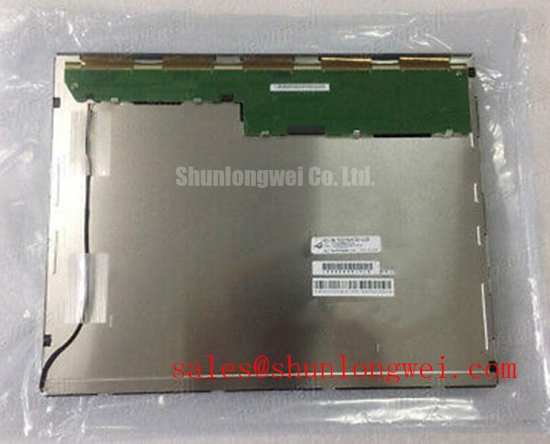
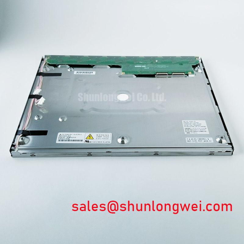
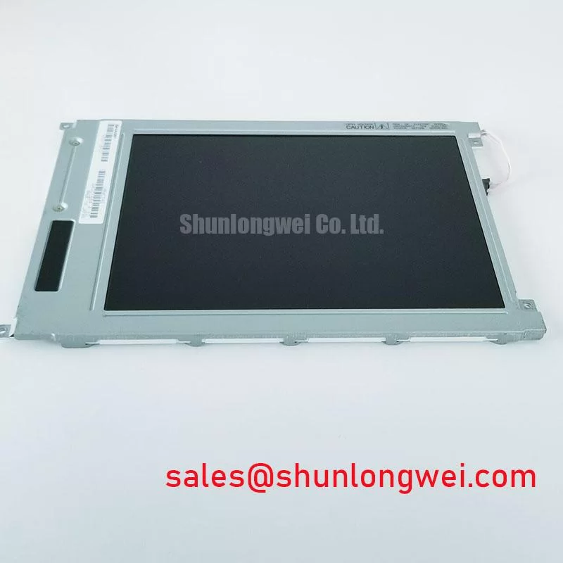
The P650HVN05-0 is an AUO TFT-LCD active-matrix color display module. Replacement assessment must cover the panel assembly, host controller, backlight circuitry, and enclosure together. Matching the model designation is the starting point, not permission to reuse an undocumented cable or driver configuration.
Compare illumination uniformity before warm-up and after sustained operation while keeping the displayed image, brightness command, and observation position unchanged. Photograph any edge shadows or bright bands from the same position. As a Design Consideration, a changing pattern warrants investigation of enclosure heat distribution and mounting pressure, rather than an immediate conclusion that the optical films have buckled.
Check whether narrow frame edges sit beside concentrated heat sources or obstructed ventilation paths. Where the enclosure design includes aluminum heat-spreader rails, evaluate their contact surfaces, mechanical clearance, and temperature distribution. Rail dimensions and attachment methods belong to the enclosure design; they are not established P650HVN05-0 installation specifications. Avoid transferring concentrated clamping loads through the display frame while improving heat removal.
Surface reflections require a separate assessment from backlight uniformity. Evaluate the assembled display under representative ambient illumination, including its protective window, rather than treating a dark-room contrast measurement as proof of sunlight readability. Anti-glare and anti-reflection treatments address different optical effects, and neither should be attributed to this model without its surface specification.
The reference on Viewing Angle Characteristics in LCDs explains why perceived contrast changes with observation direction. For an installed panel, repeat the visibility check from actual operator positions. Do not interpret off-axis contrast loss alone as backlight deterioration, and do not assign a particular optical-film material or LED lifetime classification to this module without supporting manufacturer data.
Optical Luminance Degradation Curve & CCFL-to-LED Modernization Retrofit Pathways
Track brightness changes using a repeatable image and measurement position, with ambient illumination controlled and the brightness command recorded. As an Engineering Recommendation, compare readings at similar stabilized operating conditions; a single dim-screen observation cannot distinguish source aging from altered dimming commands, supply instability, or optical contamination.
Identify the installed backlight assembly and its driver through the panel and equipment documentation before considering modernization. A CCFL-to-LED conversion is a system redesign, not an assumed feature or approved upgrade path for P650HVN05-0. It changes electrical loading, control behavior, optical distribution, and potentially the mechanical assembly. Acceptance therefore requires evaluation of the complete modified display.
For a constant-current LED driver, inspect the relationship between brightness commands, enable signals, output behavior, and any documented fault indication. Open-load or short-load protection can interrupt illumination, but a shutdown alone does not identify the failed element. Measure the relevant signals against the driver's specified operating conditions before assigning the fault to the panel.
The G121X1-L04 is another display model for separate system evaluation, not a backlight-driver accessory for P650HVN05-0. Likewise, G121SN01 V1 belongs in a cross-model assessment only after its mechanical and electrical requirements have been compared.
| Assessment item | P650HVN05-0 | G121SN01 V1 | G121X1-L04 |
|---|---|---|---|
| Role in this assessment | Target AUO TFT-LCD module | Separate display candidate | Separate display candidate |
| Dimensions, resolution, interface, and supply | Consult datasheet | Consult datasheet | Consult datasheet |
| Replacement status | Reference assembly | Direct interchangeability not established | Direct interchangeability not established |
Evaluate dimming across the intended operating range for visible flicker, unstable brightness, and acoustic noise. PWM frequency and minimum usable duty cycle must follow the selected driver and system validation, not a generic setting. Brightness retention, service life, and MTBF describe different properties; none can be assigned a numerical value here from an unsupported retrofit assumption.
Display Signal Synchronization & Logic Power Rail Verification
Resolve the P650HVN05-0 connector pinout and signal-interface specification before connecting a controller or testing synchronization. Do not assume that this panel accepts a parallel TTL RGB bus. Parallel RGB and LVDS use different electrical signaling, so connector resemblance is not evidence of compatibility.
As a Design Consideration, measure the logic supply at the panel connector during startup and steady operation, then compare its behavior with the specified power sequence. Check that valid image data, panel power, and backlight enable occur in the required order. A stable supply at the power board does not exclude voltage loss or intermittent contact at the display connection.
When the documented interface uses differential signaling, preserve the required routing characteristics through the controller, cable, and connector. Assess clock quality and data timing at the receiving end under representative operating conditions. JEIDA/VESA mapping is relevant only where the controller and panel documentation specify it; incorrect mapping can alter displayed colors without proving a damaged panel.
Field Alert: Disconnect power and allow stored energy to dissipate before inserting or removing display connectors.
For AGV or forklift telematics display evaluation, designers should verify available installation space, enclosure protection, vibration loading, and controller compatibility before selecting this module. The model designation does not establish vehicle qualification or cold-start performance.
Mechanical Stress Prevention & Glass Substrate Fault Assessment
Inspect the mounting support for uneven seating, trapped cables, and fasteners that pull the display frame out of plane. As an Engineering Recommendation, correct the support geometry rather than using tightening force to flatten the assembly. Internal driver-bump construction is not established here, and visible line defects cannot identify a microscopic fracture by themselves.
Run full-screen red, green, and blue test images through a compatible controller and record persistent lines, missing regions, or color errors. Compare the pattern with a known-good signal path where practical. Keep the panel supported during testing; pressing the glass or twisting the frame is not a controlled diagnostic method.
For a dark screen, an oblique external light can help reveal whether an image remains present. A visible image directs attention toward illumination and its control path, but does not isolate a particular failed part. No visible image warrants checking image delivery and panel power as well. The The Ultimate Guide to Industrial TFT LCD Technology provides broader context for these distinctions.
After correcting a cable or mounting fault, repeat the image test with the enclosure assembled and through the equipment's intended operating conditions. Record whether the defect remains fixed, changes with temperature, or returns when the enclosure is closed; use those observations to select the next electrical or mechanical check without assigning an unsupported failure cause.