
Content last revised on October 13, 2026
Suppressing Acoustic Capacitor Buzz & EMI Emissions across 200 Hz to 1 kHz PWM Frequencies
Compare backlight current, brightness behavior, and audible noise while changing the existing controller’s dimming command. A brightness-dependent buzz can originate in the driver board, its passive components, or mechanically coupled enclosure parts; listening near the display does not isolate the source. As a Design Consideration, correlate the sound with the driver waveform and inspect whether the noise changes when the enclosure mounting condition changes.
The PWM frequency range named in this heading is an evaluation context, not a prescribed operating range for this panel. Frequency selection should account for the documented dimming input, driver response, minimum controllable pulse width, and equipment viewing conditions. Increasing frequency alone does not guarantee quiet operation or eliminate visible modulation. Verify brightness progression across the intended adjustment range, especially near the lowest usable setting, where driver settling and command resolution can affect consistency.
Keep the backlight power circuit separate from the image-data investigation. Cold-ignition voltage belongs to a particular lamp-and-inverter arrangement and must not be transferred to an unidentified backlight connection. Likewise, a constant-current driver’s dimming ratio is a driver characteristic, not an automatic property of the LCD module. Integration should follow the panel’s specified backlight architecture and the matching driver’s electrical requirements.
For an emissions investigation, observe whether display artifacts follow dimming transitions, cable movement, or another switching load in the equipment. As an Engineering Recommendation, assess driver return paths and coupling into the display harness before changing filtering components. Any change should be checked for effects on brightness control and startup behavior. Panel operation does not establish whole-equipment EMC compliance, and backlight lumen maintenance should not be treated as interchangeable with module MTBF or guaranteed service life.
Logic Supply Voltage Sequencing (3.3V/5.0V) to Eliminate Driver IC Latch-Up Risks
Capture the panel supply, interface activity, and backlight-enable signal during both startup and shutdown, using the connector reference defined by the panel documentation. The voltage examples in this heading are not selectable supply options for the G215HAN01-3. Apply the specified rail and compare its rise, settling, and removal sequence with the required timing rather than borrowing settings from another AUO panel.
As a Design Consideration, interface signals driven into an unpowered receiver can create unintended current paths. Check what the controller outputs while its own supply starts, resets, or collapses. A white screen, intermittent startup, or retained image after shutdown can involve supply sequencing, missing video, backlight control, or controller configuration; none of these symptoms independently proves driver latch-up. Repeat the observation through the equipment’s actual power cycle, including its normal shutdown command.
Where the verified interface is LVDS, compare the transmitter configuration with the panel’s channel arrangement, color depth, clock requirements, and data mapping. JEIDA and VESA mapping differences can produce incorrect colors or gradation even when the cable seats correctly. Split images or unstable regions also warrant checking timing and channel assignment. Use known test patterns to distinguish a mapping problem from noise-related corruption instead of adjusting several controller settings simultaneously.
Pro Tip: Preserve differential-pair symmetry and avoid unnecessary routing discontinuities, then validate clock and data integrity at the receiver under the equipment’s operating conditions. This is a Design Consideration, not a model-specific trace-length prescription. Cable construction, connector transitions, and transmitter characteristics determine the appropriate routing and timing budget.
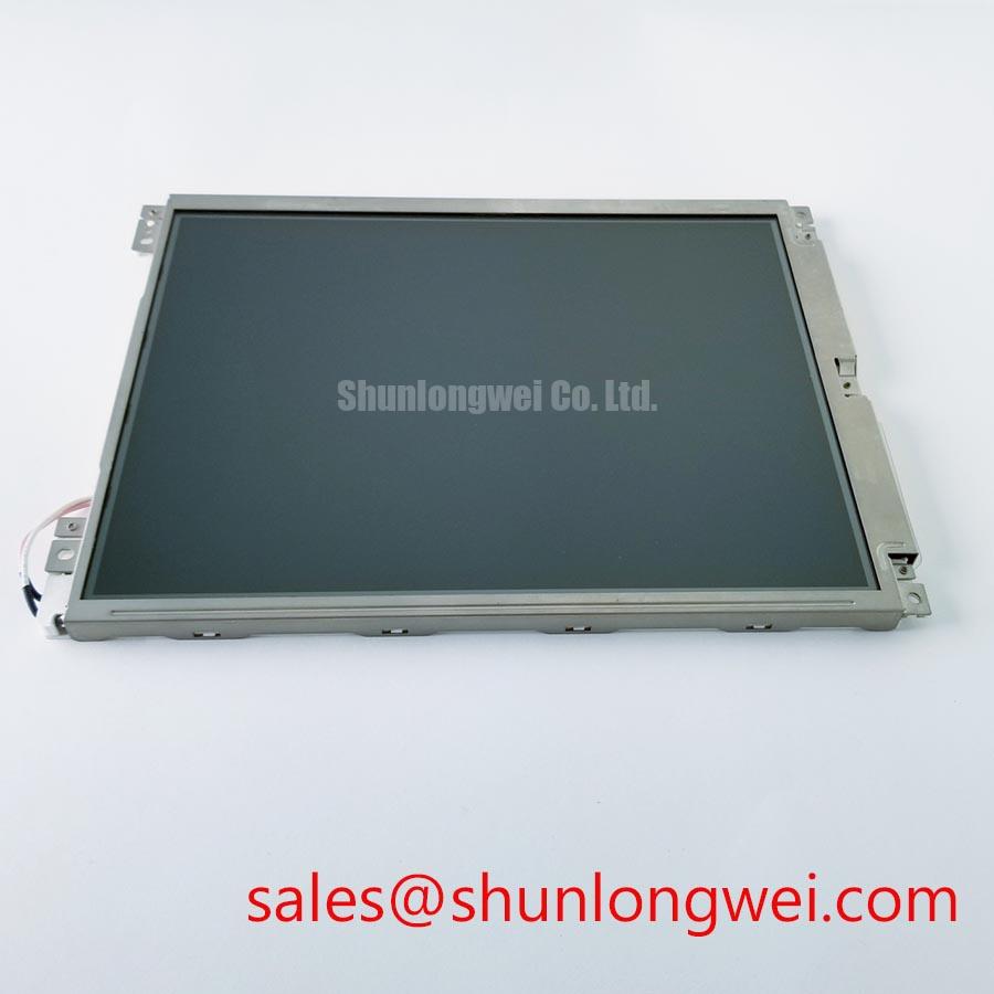
For a factory automation machine-tool HMI operator terminal, replacement approval should include readable text, correct alarm colors, and stable refresh behavior under the intended ambient lighting. Dark-room contrast does not establish sunlight readability: cover-glass reflections and installation angle affect the assembled result. The separate LQ10D213 product page can support a broader display comparison, but it is not evidence of a same-size, same-resolution, or electrically interchangeable replacement.
Thermal Expansion Clearance Sizing across Heavy Industrial Metal Enclosure Cutouts
Check the enclosure opening against the panel outline drawing and identify where the frame is actually supported before tightening the assembly. Clearance must accommodate drawing tolerances, enclosure variation, cable exit geometry, and differential thermal movement. As a Design Consideration, a bezel that presses against the viewing area can introduce stress even when the mounting holes appear aligned.
Establish fastening requirements from the specified mounting features rather than assigning a generic screw torque to the module. Screw length, engagement, support surfaces, and bracket stiffness all influence the installed load. Bring the frame into position without using fasteners to pull a misaligned bracket flat. Inspect the image before and after final fastening with uniform light and dark patterns; a mounting-dependent change in uniformity warrants checking contact pressure and support geometry.
Route the display harness so that enclosure assembly does not pinch it or pull against the connector. Where the harness includes a flexible printed section, bending should respect its documented geometry and avoid repeated flexing at the termination. Do not assign a bending-life claim without the cable supplier’s test conditions. Connector locking features should be fully engaged, with strain relief carried by the harness support rather than the electrical contacts.
For equipment exposed to vibration, evaluate the assembled bracket, harness retention, and connector support together. Static fit is not proof of dynamic suitability. As an Engineering Recommendation, inspect for movement or fretting after the equipment’s relevant qualification test and compare image behavior before and after testing. Differential-pair impedance and skew requirements belong to the validated interface design; enclosure constraints should not force cable substitutions that compromise that design.
The explanation of polarizers and light modulation in Liquid-Crystal Display (LCD) Polarizers and Optical Glass helps distinguish optical effects from electrical image faults. It does not establish this model’s coating or internal materials. Evaluate the assembled optical stack directly, including reflections, pressure-sensitive uniformity changes, and contamination between the panel and protective window.
Preventing Frame Lag & Image Smearing in Cryogenic Storage & Outdoor Industrial Facilities
Separate delayed pixel transitions from delayed image delivery by comparing moving test patterns with the controller’s output timing at the intended temperature. Liquid-crystal response generally slows as temperature falls, while controller buffering or application refresh delays can produce a different kind of apparent lag. As a Design Consideration, observe both the transition trail and the arrival of new frames before choosing a corrective action.
The environmental extremes associated with this topic are not qualification limits for the G215HAN01-3. Keep operating tests within the panel’s documented limits, and distinguish storage exposure from powered operation. Record panel temperature and stabilization conditions rather than relying only on chamber air temperature. The installed enclosure can change the panel’s thermal conditions, particularly when nearby electronics dissipate heat.
Do not apply undocumented overdrive settings as a universal cure for cold image smearing. Controller-side compensation should preserve acceptable transitions across the approved temperature range and be checked for overshoot or altered colors. For shutdown testing, observe whether video removal, panel power removal, and backlight extinction follow the specified order. Residual imagery should be evaluated separately from persistent image retention during prolonged static display.
Long-duration interface testing should include representative fixed labels, contrasting borders, and changing content. As an Engineering Recommendation, assess content movement or screen-management features where the application permits them, then examine retention under repeatable viewing conditions. The Ultimate Guide to Industrial TFT LCD Technology provides broader context for separating response time, image retention, backlight aging, and reliability terminology.
After temperature transitions, inspect connector seating, frame alignment, and optical uniformity before attributing every change to the liquid crystal. Avoid inferring sealant composition or seal reliability from the module’s appearance. Repeat the same image sequence after thermal stabilization; this comparison helps determine whether the remaining issue follows temperature, controller behavior, or assembly stress.