

Content last revised on September 25, 2026
Mitigating Gray-to-Gray Response Time Escalation during Cold-Start Machine Power-Up
During a cold start, maintenance personnel should first confirm that the display receives the intended supply and data signals in the sequence specified by the original equipment manufacturer. Liquid-crystal response can become slower at low temperature because the panel material changes optical state less quickly. That behavior is a general LCD design consideration and is not an additional factory rating for AA170EC01.
For a CNC operator panel or robot teach pendant, observe the screen during the complete machine boot sequence rather than judging performance from a single frozen image. Record whether the image appears after the controller, whether characters smear during rapid cursor movement, and whether the symptom changes as the cabinet reaches its normal operating condition. A slow image may also involve the host controller, timing configuration, cable integrity, or backlight behavior, so the display should not be assigned a single cause without signal verification.
The system integrator should verify the original panel documentation for the required interface type, clock relationship, data hold timing, supply voltage, enable signals, and any power sequencing requirements. The supplied factory information for AA170EC01 does not confirm a particular TTL or LVDS pin assignment, so those details must not be inferred from the model number. If an oscilloscope is used, compare the suspect assembly with a known-good signal path and check the timing across the intended temperature window.
Thermal cycling also places practical demands on the bezel, gasket, cable bend radius, and mounting frame. The panel should be supported evenly, with no localized pressure on the active viewing area. A compressed or displaced sealing gasket can allow dust ingress or create uneven mechanical loading. Any cold-start qualification should therefore examine both image response and the physical condition of the perimeter seal after repeated equipment start and stop cycles.
AA170EC01 should not be assigned a specific operating range, response-time value, or cold-start compensation setting unless that value is confirmed by the applicable Mitsubishi Electric documentation. Designers should test the complete display assembly under the actual cabinet temperature profile and verify readable text, stable synchronization, and acceptable transition behavior before release.
Dynamic Contrast Ratio Stabilization & Liquid Crystal Birefringence Temperature Tracking
Contrast and viewing performance in an industrial HMI depend on the LCD cell, polarizer condition, front-surface treatment, backlight, viewing angle, and surrounding illumination. The verified information available for AA170EC01 identifies its TFT LCD module category but does not provide a confirmed contrast ratio, viewing-angle specification, anti-glare treatment, anti-reflective coating, or panel technology classification. These values should be taken from the original technical documentation rather than estimated from the model designation.
When assessing a panel for a CNC operator station, inspect the display with the cabinet lighting in its normal condition. Check dark areas, pale gray text, alarm colors, and fine characters from the operator’s normal standing position. Bright overhead lighting or sunlight entering through a plant window can reduce perceived contrast even when the electronic image signal is correct. A front-surface reflection problem may therefore require enclosure or hood evaluation rather than a change to the display signal.
Temperature can alter the optical behavior of liquid crystal material and may shift the appearance of gray levels during warm-up. The practical test is to display representative machine screens at cold start, during temperature stabilization, and after the cabinet reaches its normal operating condition. Compare the same screen capture or test pattern at each stage. Any conclusion should account for the host graphics controller, backlight output, ambient illumination, and camera exposure if photographic records are used.
For a robot teach pendant, viewing angle is especially important because the operator may hold the unit below, above, or to the side of the normal axis. However, a symmetric viewing cone such as 85° in four directions must not be attributed to AA170EC01 without an official source. The integrator should verify the published viewing-angle data and confirm that critical alarms remain distinguishable from the intended working positions.
The front window, protective overlay, and gasket should be inspected for haze, scratches, trapped dust, or uneven contact. Cleaning procedures should follow the equipment manufacturer’s instructions and should avoid solvents that may attack the display surface or sealing materials. If the panel is installed behind a protective cover, the optical stack created by that cover should be tested as part of the assembly because reflections can change after installation.
For broader background on industrial panel selection and display behavior, engineers can consult The Ultimate Guide to Industrial TFT-LCD Technology. The article provides general engineering context; it does not replace the Mitsubishi Electric documentation for AA170EC01.
Diffuser Film & Prism Sheet Thermal Buckling Prevention under Continuous Full-Duty Operation
Continuous operation should be evaluated at the level of the complete display assembly. Heat generated by the panel electronics, backlight, controller, and nearby cabinet components can create local temperature differences. These differences may affect image uniformity, mechanical fit, or the appearance of optical layers. The available factory data does not confirm the internal diffuser construction, prism-sheet material, LED configuration, backlight lifetime, L70 value, B50 value, or MTBF for AA170EC01, so those figures should not be added to a purchasing specification without documentation.
During inspection, look for localized brightness variation, expanding bright areas, intermittent illumination, or changes that follow cabinet temperature. Such observations can involve the display module, backlight driver, cable connection, or power source. Compare the screen at startup and after normal full-duty operation, then inspect the cabinet airflow and the clearance around the display frame.
An aluminum heat spreader rail or additional thermal interface should not be added automatically. Any mechanical thermal modification can introduce pressure, grounding, electromagnetic, or service-access issues. If the equipment design requires heat spreading, the system engineer should evaluate the complete thermal path and confirm that the solution does not deform the panel frame or load the active area unevenly.
The same caution applies to dimming control. The available AA170EC01 information does not confirm a PWM input, PWM frequency, duty-cycle range, constant-current LED driver, or CCFL interface. The system integrator should verify the required backlight architecture from the original panel documentation. If external dimming is used, the driver waveform, visual flicker, acoustic behavior, and brightness linearity should be checked with the installed controller rather than assumed from general LCD practice.
Backlight troubleshooting should begin with non-invasive observations. Confirm whether the image is present with reduced illumination, check the driver enable state where documented, inspect connectors for heat or oxidation, and compare supply behavior with a known-good unit. An open or short indication from a host driver may identify a problem in the backlight circuit, but it does not by itself prove that the LCD module is defective.
Maintenance Note: Inspect the cabinet airflow path and display sealing gasket during scheduled service, because blocked ventilation or uneven gasket compression can increase thermal stress and create avoidable display faults.
High-Voltage Striking Potential & Secondary Coil Insulation Testing
Do not apply a high-voltage backlight test to AA170EC01 unless the original Mitsubishi Electric documentation explicitly identifies the required circuit and test method. The verified product information does not confirm a CCFL assembly, ignition voltage, secondary-coil construction, LED driver, PWM dimming range, or insulation-test voltage. Values associated with other display generations must not be transferred to this model.
For field service, begin by identifying the installed backlight architecture from the original equipment documentation and the associated driver board. A CCFL system and an LED system require different measurement methods, safety controls, fault interpretation, and replacement procedures. If the documentation identifies a high-voltage section, qualified personnel should isolate power, follow the equipment service procedure, and use measurement equipment rated for the circuit under test.
When the display is dark, separate image-path checks from illumination-path checks. A visible image under controlled illumination can suggest that the graphics path is active while the backlight path requires further evaluation, but this observation is not a definitive diagnosis. If there is no image, verify the host output, cable seating, enable sequence, and supply conditions before concentrating on the backlight.
For an industrial CNC panel or robot teach pendant, vibration and repeated cable movement can affect connectors and harnesses over time. Inspect strain relief, locking features, bend points, and contact seating. Do not pull on a flex cable or insert a display connector while the equipment is energized. A replacement assembly should be tested with the original controller and cable arrangement before the bezel is fully secured.
Insulation testing must remain limited to the voltage, duration, and connection points specified by the applicable service documentation. Excessive test voltage can damage display electronics, protective components, or the backlight circuit. The system engineer should also verify that any insulation test is compatible with the host machine’s grounding and safety procedure rather than treating the LCD module as an independently certified system component.
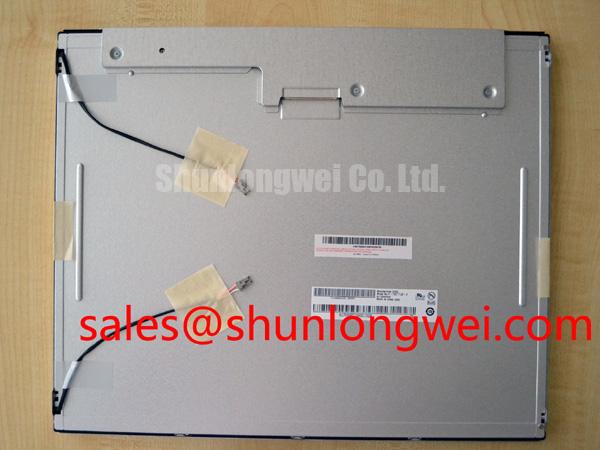
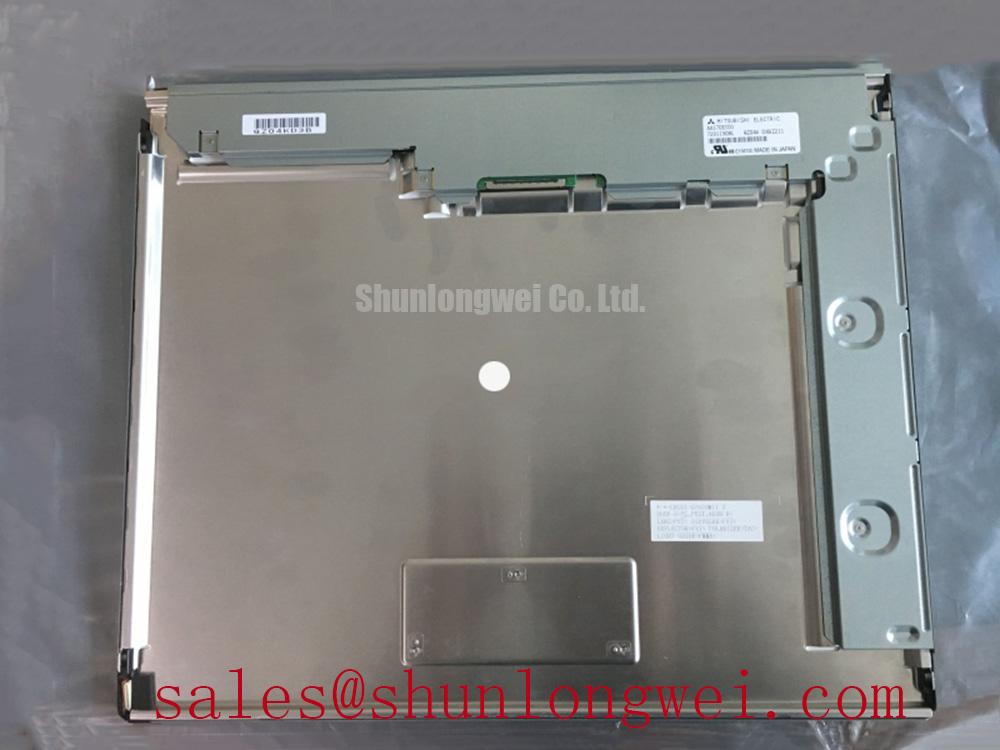
AA170EC01 is identified as a Mitsubishi Electric TFT LCD Display Module for evaluation in industrial HMI assemblies. Before procurement or installation, confirm the original interface, power requirements, mechanical drawing, optical specifications, backlight architecture, temperature ratings, and service documentation for the exact equipment in which it will operate.