

Content last revised on October 15, 2026
High-Humidity Storage Margins (60°C / 90% RH) & Delamination Prevention Protocols
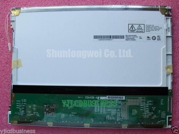
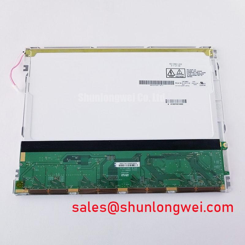
Inspect the panel perimeter, connector contacts, and visible optical surfaces for moisture residue, edge lifting, or uneven haze before applying power after damp storage. The 60°C / 90% RH condition in this section is an environmental evaluation reference, not an established B104SN03-V2 storage rating. A qualification plan should define exposure duration, condensation control, recovery conditions, and acceptance criteria from the applicable product specification.
Design Consideration: allow a cold assembly to stabilize in a controlled environment before electrical testing when condensation is possible. Record whether haze remains stationary, changes during recovery, or appears only with illumination. These observations help distinguish surface contamination from an optical stack concern without assigning a specific internal material or seal construction to this model. Avoid pressing the active area to investigate an edge defect.
At low temperature, increased liquid crystal viscosity can slow gray transitions. Evaluate moving edges and intermediate gray patterns after temperature stabilization, keeping the image source and backlight setting consistent. A room temperature response measurement does not establish cold performance. Any proposed thermal cycling should stay within the approved component and assembly limits, with perimeter appearance and image uniformity checked before and after exposure.
For interface integration, identify the actual connector pinout and signaling standard before interpreting waveform measurements. Where the host uses LVDS, differential impedance, pair skew, termination, and receiver timing need coordinated verification against the transmitter and receiver requirements. JEIDA and VESA mapping require attention only where the confirmed interface supports those formats. Applying either mapping assumption without checking the interface can produce incorrect colors despite an apparently stable image.
Pro Tip: When routing a confirmed differential interface, control pair geometry and relative delay, then verify receiver timing with the production harness connected. For enclosure exposure and environmental test planning, Industrial Display & HMI Solutions provides broader integration context; acceptance limits should remain tied to the actual display and finished equipment.
Constant Luminance Output Control & L70/B50 Reliability Verification
Measure luminance after thermal stabilization and repeat the measurement with the same image, viewing geometry, and ambient illumination. Design Consideration: a brightness change can originate in the illumination supply, dimming command, thermal behavior, optical contamination, or the display itself. Comparing these conditions independently is more useful than increasing drive to compensate for an unexplained loss.
Confirm the backlight architecture before selecting its power stage. In an LED illumination system, constant current regulation controls electrical drive, while perceived brightness also depends on temperature and the optical path. Driver efficiency concerns input power and losses; it does not establish panel luminance or service life. Open load protection, short circuit protection, overvoltage response, and fault reporting belong to the selected driver implementation and require verification at that circuit.
If illumination cycles or shuts down, correlate the enable signal, dimming input, supply behavior, and available fault output. Use the driver's documented fault sequence to interpret the event. Repeatedly resetting protection can obscure the original operating condition. A compatible test load and the prescribed measurement arrangement can help separate a supply problem from a backlight load problem.
L70 describes a lumen maintenance threshold, while B50 describes a population criterion under a defined reliability framework. Neither designation establishes a B104SN03-V2 lifetime, and a brightness maintenance endpoint is different from MTBF. A meaningful reliability comparison needs the backlight supplier's test conditions, drive conditions, temperature reference, and statistical method. No numerical service life is assigned here.
Design Consideration: evaluate any enclosure heat spreader through measured temperature distribution and mechanical clearance. Its dimensions and attachment should follow the finished assembly's thermal results. Generic claims about optical material yellowing should not be attributed to this panel without material evidence. If a system requires low temperature heating, assess startup response and thermal uniformity as separate assembly functions rather than treating a heater as a panel feature.
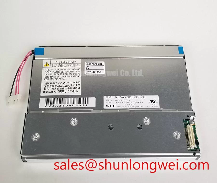
The NL8060BC31-02 is a separate display reference for comparing complete display chain requirements, including the host interface and illumination supply. It should not be treated as a backlight driver accessory. The Winstar Industrial TFT-LCD and OLED Display Modules resource offers general display technology context rather than specifications for the AUO model.
Flush-Mount Open-Frame Bezel Integration & Perimeter Gasket Shock Isolation
Check the chassis opening, support surfaces, cable exit, and connector clearance against the panel drawing before tightening the assembly. Design Consideration: a bezel should retain the module without transferring uneven compression into the viewing area. Gasket compression and fastener tightening depend on the enclosure stack, thread engagement, and mounting provisions; a generic screw torque is not a B104SN03-V2 assembly specification.
Examine uniform gray and dark images before and after installation. A change in edge brightness or localized shading can help identify assembly stress, but optical nonuniformity has several possible causes. Adjust the support arrangement through controlled assembly trials rather than flexing the panel. Cable restraint should prevent harness movement from loading the connector during enclosure closure.
The NL8060BC31-17D can be included in a sourcing comparison, with mechanical and electrical compatibility assessed independently. The following comparison identifies the evidence needed before either reference becomes a replacement candidate.
| Selection checkpoint | AUO B104SN03-V2 | NL8060BC31-17D reference |
|---|---|---|
| Product identity | AUO TFT-LCD active matrix color display module | Separate display model for comparison |
| Electrical compatibility | Consult datasheet for supply, interface, pinout, timing, and sequencing | Compare corresponding specifications before connection |
| Mechanical compatibility | Match outline, viewing area, mounting locations, and connector clearance | Check the complete dimensional drawing against the chassis |
| Optical compatibility | Establish required luminance, viewing direction, and surface treatment | Compare measured visibility under the intended installation conditions |
For a marine radar or navigation bridge console compatibility assessment, evaluate ambient reflections, viewing position, enclosure sealing, and environmental qualification at equipment level. Anti-glare treatment redistributes reflected light, while anti-reflection treatment reduces reflection through an optical coating system; neither treatment is asserted for this model. The Viewing Angle Characteristics in LCDs reference explains why contrast and color should be assessed from the operator's actual position.
Single Vertical Hairline Defect & Sub-Pixel Column Driver Open-Circuit Localization
Display solid red, green, and blue images sequentially, recording whether a vertical line remains at the same column and whether its appearance changes with the selected color. Add neutral gray and dark patterns to separate color dependent behavior from illumination nonuniformity. A persistent line can support investigation of the panel drive path, but its appearance alone does not establish an internal open circuit or a fractured connection.
Design Consideration: compare the result with a known working image source and a correctly matched harness. Inspect connector engagement with power removed, then repeat the same patterns. If the defect changes with cable position, investigate connection integrity without treating that response as proof of a single failure mechanism. Avoid pressing the glass edge or manipulating bonded connections as a diagnostic shortcut.
For a dark screen, direct a flashlight obliquely across the viewing surface and look for a faint changing image. A visible image supports further investigation of the illumination path; its absence does not independently prove a panel failure. Check image activity and illumination control separately, following the confirmed electrical interface and driver documentation.
Record the displayed pattern, line position, warmup behavior, supply stability, and illumination state in the repair report. These observations let a purchasing or repair engineer distinguish a repeatable panel symptom from a host or harness dependency and define an acceptance test for the replacement assembly.