
Content last revised on October 1, 2026
BSM111 Thermal and Electrical Checks at the DC Bus
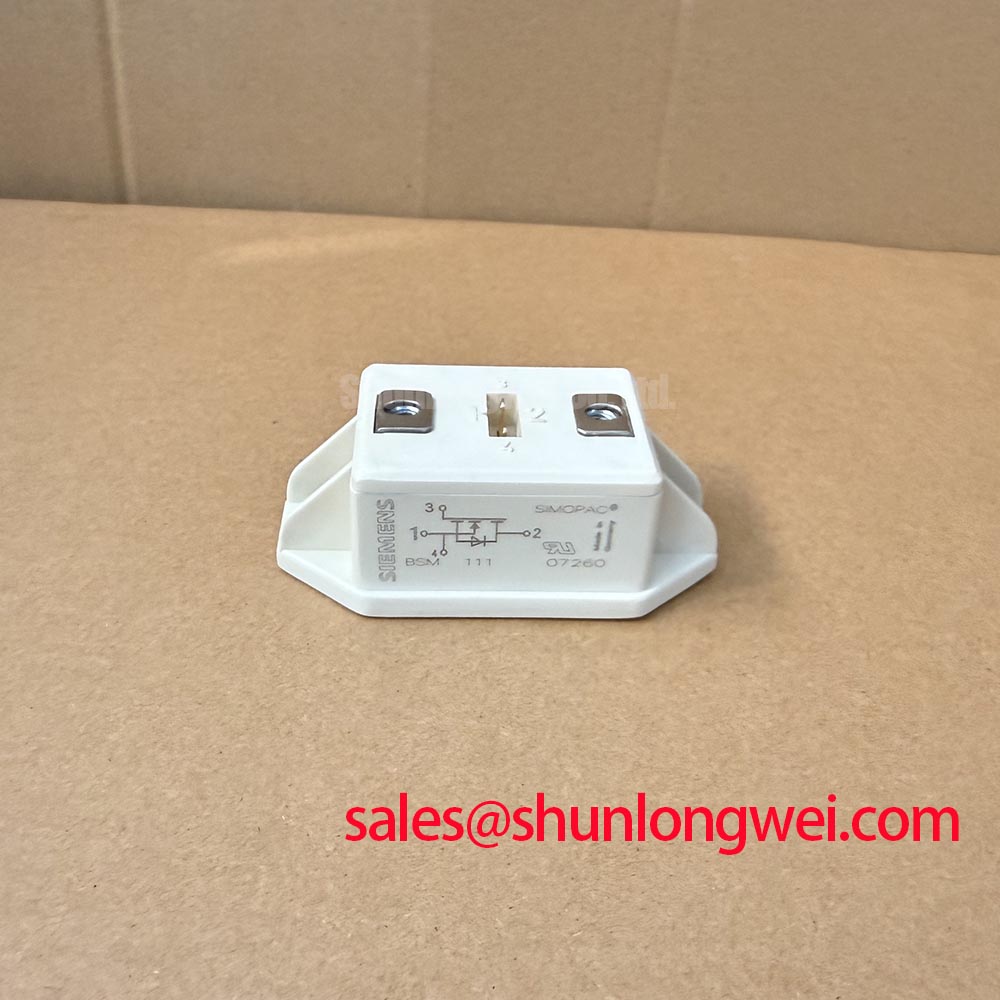
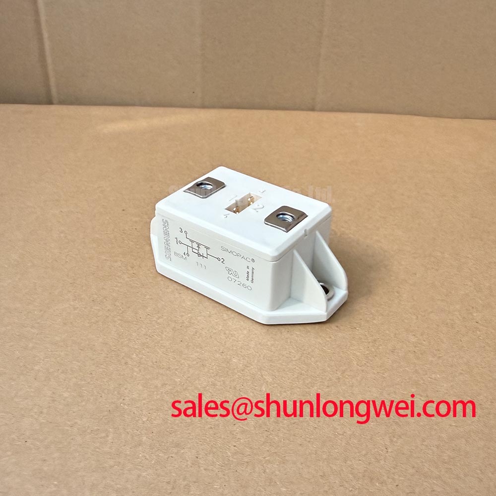
Probe the collector–emitter waveform during a controlled switching test if the drive reports a DC bus overvoltage trip. Compare the measured turn off peak with the BSM111 1100 V collector–emitter rating, an Official Specification, rather than judging the design from its steady DC bus voltage alone. Keep the probe connection short and use a measurement method appropriate for the bus potential; a long probe ground lead can distort the apparent spike.
Turn off overshoot depends on current slew rate and stray inductance in the switching path. As a Design Consideration, keep the DC link capacitor, bus conductors and module connections in a compact, balanced loop, then verify the peak at the actual operating current. Symmetrical laminated busbar geometry can help reduce loop inductance, but neither a busbar geometry nor a snubber value is an official BSM111 requirement. Select any snubber only after measuring the circuit’s ringing, losses and voltage margin.
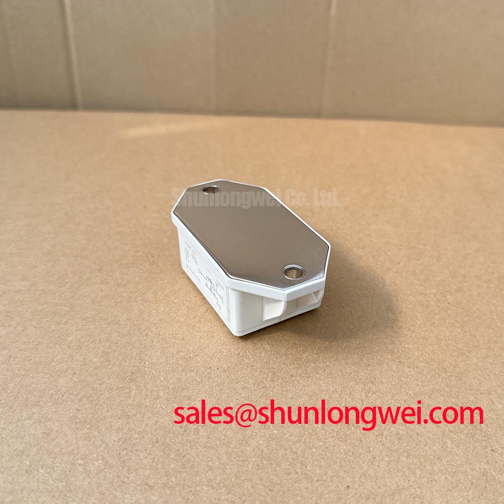
Inspect the module mounting surface and thermal interface when a drive trips after warming up. Uneven contact, cooling faults and changes in operating duty can all affect temperature; a trip alone does not identify the module as the cause. The supplied BSM111 specifications do not state transient thermal impedance or a peak junction temperature limit, so those values cannot be inferred from its 1 A current rating. For a compact industrial inverter or high speed CNC spindle drive under evaluation, use the equipment’s thermal design and the applicable device documentation to assess pulsed operation.
Benchtop Waveform Tuning and Overvoltage Trips
Capture the DC bus voltage and gate command around a deceleration trip to distinguish regenerative bus rise from a switching spike. A braking circuit, where fitted, must be evaluated against the motor, drive and resistor documentation; the BSM111 rating does not establish braking energy capacity or identify an internal braking switch. Treat the braking switch and resistor as system components whose sizing depends on the measured duty cycle and stored mechanical energy.
Check complementary gate commands at the driver outputs and at the module connections if a trip occurs during a switching transition. As a Design Consideration, interlocking and dead time should prevent simultaneous conduction without assuming that a controller setting remains adequate after propagation delays and switching behaviour are included. Confirm the result on the bench across the intended operating conditions.
When reviewing the surrounding power stage, FS75R12KT3G can be examined as a separate component reference; its ratings and circuit role must be assessed independently. For a repair comparison, BSM100GB120DLC is likewise a candidate for specification review, not a confirmed drop in replacement. Compare its terminals, topology, voltage and current ratings, mounting interface and gate drive requirements with the original equipment documentation before considering a substitution. Infineon High Power Semiconductor Solutions provides broader power device context, not a substitute for that part specific comparison.
Fault Clearing and Gate Drive Behaviour
Record the gate and collector–emitter waveforms during a controlled fault test if protection repeatedly trips at startup. Desaturation detection can indicate that a commanded on state is not developing normally, but the waveform must be assessed alongside the driver supply, load path and sensing circuit. The supplied BSM111 specifications do not establish short circuit withstand time, a desaturation threshold or a fault category; do not assign a clearing deadline from a generic IGBT example.
As a Design Consideration, coordinate fault detection with controlled turn off so that clearing current does not create excessive inductive overshoot. Validate the protection path at system level against the device’s documented limits and measured bus voltage. Inspect gate return routing, local driver supply behaviour and the collector sensing connection before changing protection timing. A gate waveform that looks orderly at the controller can differ at the module terminals because of wiring and common return impedance.
Pro Tip: Keep the gate and return paths close together, then verify turn off voltage margin with measured switching waveforms before changing the driver response. The Precision Gate Drive Design guide offers additional context for investigating ringing, Miller coupling and fault response.
Field Diagnostics of Driver Isolation and Unintended Switching
Measure the gate signal at the module terminals when an unintended pulse appears during another switch’s transition. Correlate it with the switching node waveform, driver supply and fault output; the timing can help separate coupled noise from a commanded pulse. As a Design Consideration, review gate loop layout, common return paths and the driver’s specified immunity before changing the gate off bias. Any off bias must be checked against the actual driver and device limits rather than assumed from IGBT practice.
An optocoupler or a transformer coupled driver is a system level choice, not an identified feature of the BSM111. Check the installed driver’s isolation documentation, board clearances and common mode performance against the equipment’s requirements. No isolation voltage or immunity rating for the BSM111 follows from the supplied module specifications. Infineon EiceDRIVER™ Galvanic Isolated Gate Driver ICs provides driver technology context; verify the exact fitted driver separately.
If the pulse persists, compare the driver input, output and module terminal waveforms in sequence, using the same operating condition for each capture. Keep isolation barrier and layout assessments tied to the assembled drive: a module voltage rating alone cannot establish the board’s isolation performance or the cause of a spurious gate event.