
Content last revised on September 14, 2026
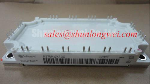
Transient Dynamics and Electrical Design: Differential Gate-Emitter Loop Routing for FS75R12KT3G
During a drive repair, trace the gate command from the isolated driver to the module before changing the power device. The gate return should be referenced to the intended emitter return used by the driver, while the high current emitter path should remain physically separate. This differential gate-emitter loop arrangement reduces the influence of common emitter inductance, which can otherwise turn load current changes into an unwanted feedback signal at the gate.
This is a Design Consideration, not an FS75R12KT3G Official Specification. Keep the gate drive path short, compact, and separate from the collector and emitter power paths. Avoid routing the gate signal alongside the switching node for long distances. Where the board uses an auxiliary emitter or control return, connect that return according to the original circuit reference rather than assuming that a nearby power emitter pad is electrically equivalent under fast switching conditions.
Turn off the DC link and use a controlled inspection process. Check for cracked solder joints, loosened terminal hardware, carbon tracking, discoloration around the gate network, and damaged isolation components. With the module disconnected from the driver, compare the gate path with a known good phase using the same test method. An unexpected resistance or capacitance difference may indicate a damaged gate resistor, driver output stage, connector, or PCB trace; it should not be treated as proof of an internal module failure without additional testing.
When commissioning, observe the gate to emitter waveform directly at the module terminals with suitable differential probing. Check the command level, rise and fall behavior, ringing, Miller plateau behavior, and the relationship between the gate waveform and collector current. Excessive ringing may arise from the complete loop, including driver impedance, connector inductance, measurement ground, and busbar geometry. Designers should adjust the gate network only after checking these external contributors and verifying switching stress under controlled load conditions.
Short circuit protection requires particular care. A desaturation or VCE(sat) monitoring circuit may be used by the system designer to detect abnormal conduction, but the correct blanking interval, fault threshold, soft shutdown profile, and isolation behavior are system determined. The supplied product data does not establish those values for this specific module. Soft turn off should be validated with an oscilloscope so that the fault current is reduced without creating an unacceptable collector emitter overvoltage.
Gate charge and Miller plateau behavior also interact with the driver’s common mode transient immunity. A fast switching edge can couple energy through the collector gate capacitance and surrounding parasitic capacitance. An isolated driver or optocoupler selected for the design should be checked for its specified CMTI and propagation characteristics. The module itself should not be described as independently compliant with a complete drive system EMC standard.
Assembly Integrity and Layout Architecture: Implementing Multi Module Parallel Current Sharing for FS75R12KT3G
Parallel operation should begin with a topology review, not with simply connecting terminals together. The power paths to each module should have comparable resistance and inductance, and the gate drive paths should be routed with similar geometry. Symmetry helps the switching events occur at similar times, while unequal wiring can cause one device to carry a disproportionate transient current before static thermal sharing becomes relevant.
A Design Consideration for parallel IGBT operation is the positive temperature coefficient commonly associated with on state voltage in the relevant operating region. As a conducting device warms, its voltage characteristic can support static current redistribution. This effect is not a substitute for matched layout, matched gate drive impedance, adequate thermal coupling, or current measurement. The exact sharing behavior depends on current, junction temperature, switching conditions, and the manufacturer’s electrical curves for the device.
For a heavy duty variable frequency AC motor drive, inspect the laminated busbar or low inductance power interconnect for equal path length and firm mechanical contact. Do not allow one parallel branch to include an extra connector, narrow copper section, or flexible lead that is absent from the other branch. Check the collector and emitter voltage at each module during switching tests, because a similar average current does not guarantee similar peak current or switching loss.
High side gate supply arrangements need their own verification. If a bootstrap supply is used, the capacitor selection must account for total gate charge, driver quiescent current, leakage, refresh time, switching duty cycle, temperature, and the permitted gate supply ripple. The required capacitance is therefore an Engineering Calculation based on the selected driver and switching sequence, not a universal value assigned to FS75R12KT3G. Designers should confirm that the bootstrap source can replenish charge during the available low side conduction interval and that the high side gate voltage remains within the driver and module documentation limits.
Do not infer a bootstrap design from the module’s 75.0 A rating. Gate charge is a switching parameter and must be taken from the applicable electrical data. A high load current can coexist with an inadequate gate supply if the driver reservoir, diode, return path, or refresh timing is poorly selected. During bench commissioning, measure the isolated supply at the driver pins while applying the intended PWM pattern and thermal operating range.
Mechanical assembly directly affects electrical reliability. The heatsink face should be clean, flat, and free from burrs or foreign material. The thermal interface should be applied consistently according to the assembly process, with no voids or contamination at the contact area. Fasteners should be tightened in the manufacturer’s specified sequence and torque range when available. For a pressure mounted arrangement using a spring or disc spring system, calibrate the applied force and inspect the spring condition rather than relying only on screwdriver torque.
After installation, record the terminal condition, cooling airflow, and measured case or heatsink temperature during a controlled load test. ⚠️ Maintenance Note: Inspect heatsink dust accumulation and thermal interface aging during scheduled service, then compare phase temperatures and terminal temperature rise under the same load.
When a different device family is being assessed for a repair, the BSM75GD120DLC may be reviewed as a separate, neutral engineering comparison. It should not be treated as a drop in substitute until voltage, current, topology, gate requirements, package dimensions, isolation, and protection coordination have all been confirmed.
Field Diagnostics and Commissioning: Overvoltage Trip Prevention via Fast Switching in FS75R12KT3G Topologies
When a drive trips during acceleration or deceleration, first capture the DC link voltage, gate waveform, phase current, and fault timing together. A trip may involve braking energy, control timing, busbar inductance, a measurement error, or a protection circuit response. Looking only at the fault code can conceal the interaction between the motor, braking path, capacitor bank, and IGBT switching event.
In a variable frequency AC motor drive, deceleration energy can return to the DC link faster than the capacitor bank or front end can absorb it. The braking IGBT and ballast resistor must therefore be evaluated from the motor inertia, speed profile, braking duration, duty cycle, DC link operating range, resistor pulse capability, and enclosure cooling. These are system design parameters. The FS75R12KT3G current and voltage ratings identify the device class, but they do not determine the correct braking resistor power or energy rating.
During commissioning, verify that the braking command reaches the intended driver, that the braking transistor is not receiving an unintended continuous command, and that the resistor connections are secure. Inspect the resistor for thermal discoloration and measure its resistance only after isolation and discharge procedures have been completed. A faulty DC link voltage sensor can also create inappropriate braking behavior, so compare the controller reading with an appropriately rated independent measurement method.
Fast switching can produce a short overvoltage pulse even when the average DC link reading appears normal. Minimize the commutation loop area and keep the turn off path controlled. The peak collector emitter voltage is influenced by the DC link voltage, stray inductance, and current change rate; the resulting margin must be verified on the actual assembly with a suitable high voltage probe. Snubber or clamp selection should follow measured waveform energy and the switching conditions rather than a generic component value.
Fault protection should be commissioned at reduced energy first. Confirm the response of desaturation detection or VCE(sat) monitoring, the fault latch, the soft shutdown action, and the reset sequence. Short circuit safe operating area and fault duration must be confirmed from the applicable Infineon documentation. Without an authoritative source for a specific short circuit time or lifetime figure, no field failure rate or guaranteed operating duration should be assigned to this product page.
For the auxiliary rectifier or front end of a related power topology, engineers may also review BSM75GB120DN2 as a separate product reference. Its electrical and mechanical suitability must be assessed independently rather than assumed from the use of a similar voltage class.
FS75R12KT3G Operational Boundaries: Evaluating DC Link Capacitance Bank Layout and Low-ESR Limits
Inspect the DC link capacitor bank, busbar joints, and switching loop as one electrical structure. A capacitor can retain acceptable capacitance while its connections, terminals, or internal equivalent series resistance have degraded. Look for rising ripple temperature, loose laminated connections, localized discoloration, and asymmetry between positive and negative current paths. Measurements should be made with the equipment isolated and discharged under the site safety procedure.
The turn off overshoot can be understood in engineering terms as the DC link voltage plus the voltage generated by stray inductance during a rapid current change. This relationship explains why a low impedance capacitor bank located electrically far from the module may offer less protection than expected. The practical objective is to place high frequency decoupling and the switching loop close together, reduce broad current loops, and verify the measured peak against the 1200.0 V device boundary and the applicable transient specification.
Plan the positive and negative bus conductors as a closely coupled pair where the mechanical construction permits. Symmetrical planar busbar geometry can reduce loop inductance and improve the consistency of switching behavior between phases or parallel branches. The target inductance and allowable clearance are system determined; they must be established from the switching speed, current, insulation system, DC link voltage, and measured overshoot. A numerical layout limit should not be assigned without the relevant topology and test data.
Snubber capacitors, clamps, and damping networks should be selected after identifying the frequency content and energy of the measured ringing. Confirm component pulse capability, insulation rating, thermal behavior, and physical placement. A snubber mounted through long leads may introduce enough parasitic inductance to reduce its effectiveness. Compare waveforms at the module terminals and at the capacitor bank so that the measurement distinguishes local commutation overshoot from a broader DC link resonance.
Environmental maintenance remains part of the electrical boundary. Dust can obstruct airflow and raise the thermal resistance of the heatsink, while condensation can reduce insulation margin and promote corrosion around terminals and busbar supports. Designers and maintenance teams should verify enclosure sealing, heater or dehumidification controls where applicable, and the actual temperature rise during seasonal operating conditions. These are Design Considerations, not additional Official Specification values for FS75R12KT3G.
For background on how wide bandgap devices can alter switching speed, parasitic inductance sensitivity, and gate protection requirements, consult Wide Bandgap Revolution. The article is a technology reference, while the electrical limits for this Infineon IGBT module must remain tied to the applicable manufacturer documentation and the validated drive design.