


Content last revised on April 13, 2026
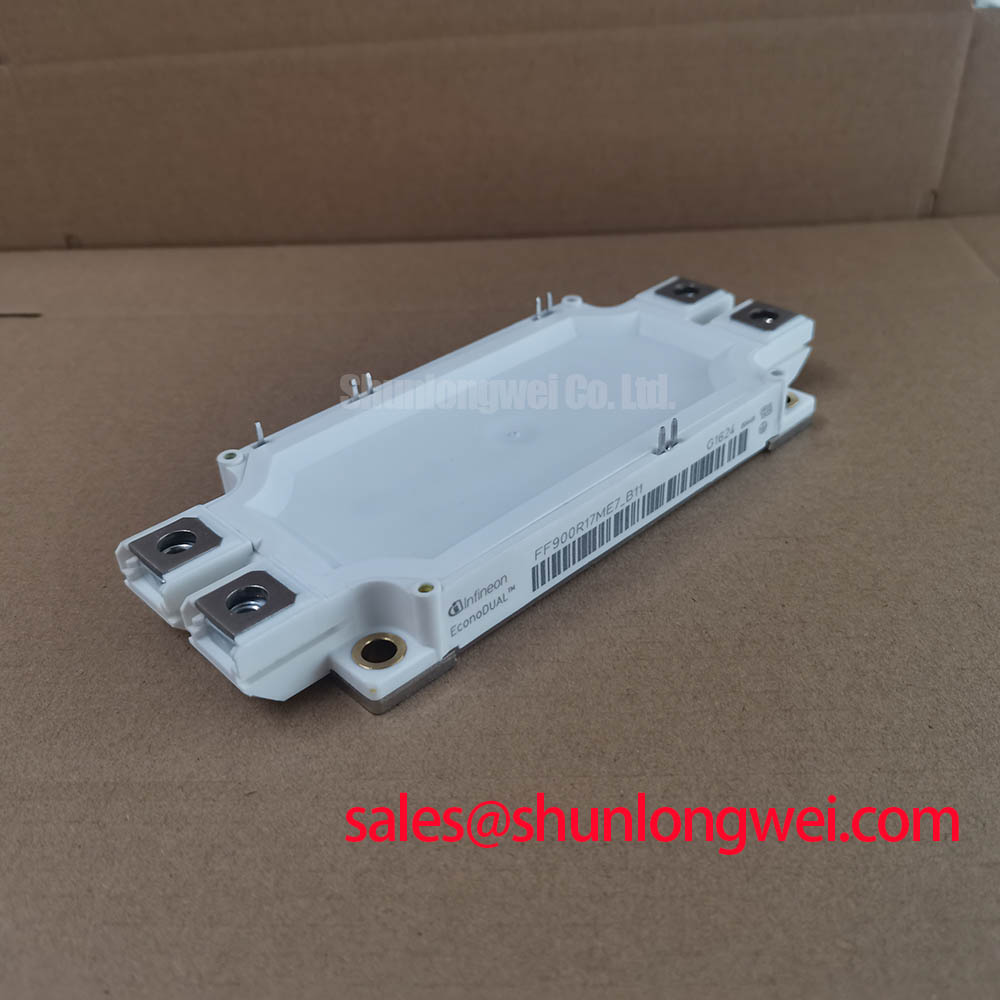
FF900R17ME7_B11: Engineering Analysis of a High-Power 1700V IGBT Module
Introduction to the FF900R17ME7_B11 High-Power IGBT
A Datasheet-Driven Overview for System Designers
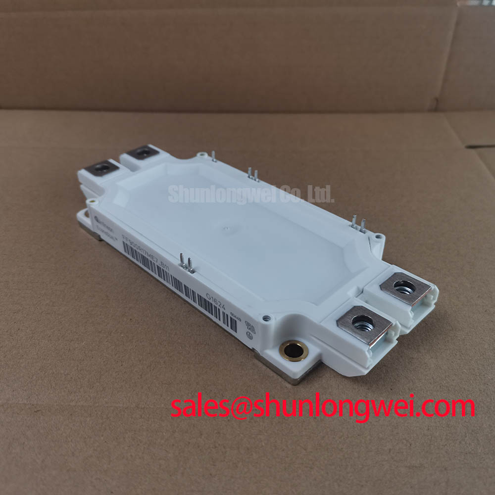
The Infineon FF900R17ME7_B11 is a high-power IGBT module engineered to deliver robust performance in demanding high-voltage inverter applications. It provides a potent combination of current handling and voltage blocking capability: 1700V | 900A | Tvj op 150°C. This module is built for exceptional power density and sustained thermal stability. It directly addresses the challenge of achieving high power conversion efficiency in systems where thermal management is a critical design constraint. For megawatt-scale converters requiring high reliability under fluctuating load conditions, this 1700V module provides a well-defined engineering solution.
Key Parameter Overview
Decoding the Specs for Thermal Performance and Efficiency
The technical specifications of the FF900R17ME7_B11 are foundational to its performance in high-power systems. The following table highlights key parameters, providing an interpretation of their engineering value. These values are extracted from the official datasheet and are critical for accurate system modeling and design validation.
| Parameter | Value | Engineering Interpretation |
|---|---|---|
| Collector-Emitter Voltage (V_CES) | 1700 V | Provides the necessary voltage margin for applications connected to 800V to 1000V DC-links, ensuring safe operation under transient overvoltage conditions often seen in large-scale industrial drives. |
| Continuous Collector Current (I_C nom) | 900 A (at T_C = 80°C) | This high current rating is the cornerstone of the module's ability to drive multi-megawatt loads. It signifies the module's capacity to handle substantial power flow, directly translating to higher output power for the end application. |
| Collector-Emitter Saturation Voltage (V_CE sat) | Typ. 2.15 V (at I_C = 900 A, T_vj = 150°C) | A lower V_CE(sat) is like having less friction in a mechanical system. This value indicates low conduction losses, meaning less energy is wasted as heat when the switch is fully on, which boosts overall system efficiency. |
| Total Switching Energy (E_tot) | Typ. 420 mJ (at I_C = 900 A, V_CE = 900 V) | Represents the energy lost during each turn-on and turn-off cycle. The IGBT4 technology is optimized to balance this switching loss against conduction loss, a critical trade-off for designers working with specific switching frequencies. |
| Thermal Resistance, Junction-to-Case (R_thJC) | Max. 0.043 K/W per IGBT | This parameter is a direct measure of how efficiently heat can be transferred from the active silicon chip to the module's baseplate. A low thermal resistance simplifies heatsink design and is crucial for maintaining junction temperatures within safe limits under heavy loads. |
| Maximum Junction Temperature (T_vj op) | 150 °C | A high operating junction temperature provides a larger thermal safety margin, enhancing the module's robustness and reliability in environments with high ambient temperatures or during periods of peak power demand. |
For a comprehensive list of electrical and thermal characteristics, please Download the FF900R17ME7_B11 datasheet for detailed specifications and performance curves.
Application Scenarios & Value
System-Level Benefits in Megawatt-Scale Power Conversion
The FF900R17ME7_B11 is specifically tailored for high-power converter systems where reliability and power density are non-negotiable. Its 1700V blocking voltage makes it an excellent candidate for large industrial drives and renewable energy applications.
- Wind Turbine Inverters: In multi-megawatt wind turbines, the power converter must handle variable power from the generator while ensuring grid compliance. What is the primary benefit of the FF900R17ME7_B11's thermal design? Its combination of a high 150°C operating temperature and low thermal resistance provides the robustness needed to manage fluctuating power levels and harsh environmental conditions, contributing to longer service life and reduced downtime.
- Central Solar Inverters: Large-scale solar farms utilize central inverters to convert DC power from vast solar arrays to AC power for the grid. The high current rating of 900A allows designers to achieve higher power ratings per inverter, reducing the overall number of units and system complexity.
- Medium Voltage Drives (MVDs): In industries such as mining, marine, and manufacturing, large motors are controlled by MVDs. The FF900R17ME7_B11 enables the design of compact and efficient power stages within these drives, controlling massive motors with precision while minimizing energy waste.
In these applications, the engineering challenge often revolves around dissipating heat effectively to ensure long-term reliability. The module's excellent thermal characteristics directly translate into a more manageable thermal design, potentially allowing for smaller, more cost-effective heatsink solutions. While this module is ideal for very high power levels, for systems in a similar voltage class but with lower current demands, the related FF600R17ME4 may offer a more tailored solution.
Technical Deep Dive
Anatomy of a High-Performance Switch: IGBT4 and Emitter Controlled Diode
The performance of the FF900R17ME7_B11 is rooted in its internal components, primarily the Infineon TrenchSTOP™ IGBT4 and the Emitter Controlled Diode. This combination is engineered for a balanced performance profile crucial for high-power, medium-frequency applications. The IGBT4 technology represents a mature and highly reliable platform known for its low collector-emitter saturation voltage (V_CE(sat)). Think of V_CE(sat) as the "voltage toll" paid when current flows through the switch. The low 2.15V typical value at full load means lower power is dissipated as heat during the 'on' state. This is a critical factor for improving the overall efficiency of a Variable Frequency Drive (VFD) or solar inverter, directly impacting operating costs over the system's lifetime.
Complementing the IGBT is the Emitter Controlled Diode. This freewheeling diode is optimized for soft switching behavior and low reverse recovery losses. This ensures that during the switching transitions, voltage overshoots and electromagnetic interference (EMI) are minimized, simplifying the design of snubber circuits and improving the system's electromagnetic compatibility. The synergy between the low-loss IGBT4 and the soft-recovery diode allows designers to push for higher power density without compromising on reliability or creating new EMI challenges. For a deeper understanding of how these internal components influence system design, exploring resources on IGBT failure analysis can provide valuable context.
Frequently Asked Questions (FAQ)
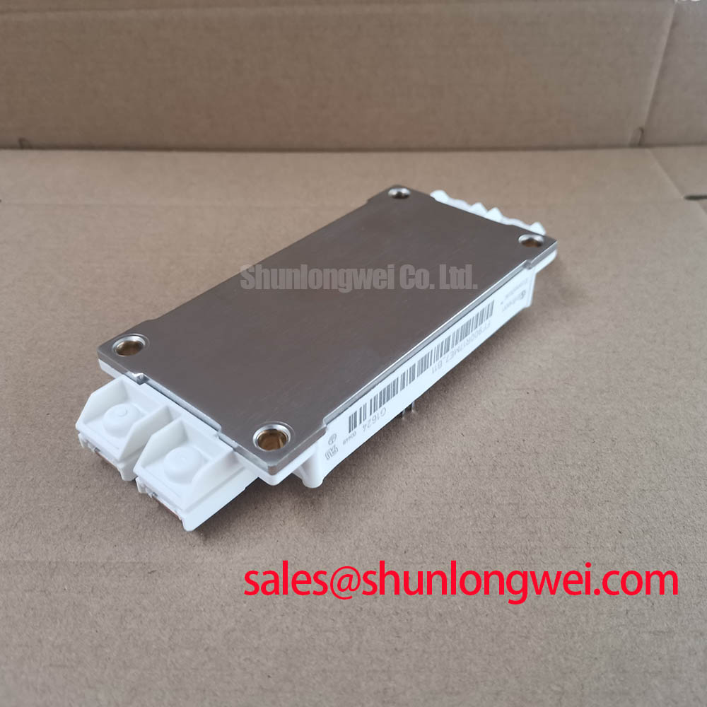
How does the IHM-B housing of the FF900R17ME7_B11 contribute to system reliability?
The IHM-B (Insulated High-Power Module B-Series) housing is an industry-standard package designed for high-current applications. Its robust mechanical construction ensures reliable pressure contact to the heatsink, facilitating low thermal resistance. Furthermore, its standardized footprint and terminal layout simplify busbar design and allow for straightforward paralleling of modules to achieve even higher power outputs, a key requirement in megawatt-class inverter design.
What are the key considerations when designing a gate drive for this 900A module?
Given the high current rating, a robust gate drive design is essential for ensuring clean and efficient switching. Key considerations include providing sufficient peak gate current to charge and discharge the IGBT's input capacitance quickly, minimizing switching losses. It's also critical to have a stable gate voltage supply and a low-inductance layout to prevent parasitic turn-on. Implementing features like a Miller Clamp is also highly recommended to prevent shoot-through currents during fast dV/dt events.
An Engineer's Perspective
Final Thoughts on System Integration
From a design engineer's viewpoint, the FF900R17ME7_B11 is less about a single standout feature and more about a well-balanced execution of critical specifications. It doesn't present radical new technology but instead offers a highly dependable and powerful building block based on the proven IGBT4 platform. Its value lies in its predictability. The detailed characterization in the datasheet, combined with the module's robust thermal architecture, allows for confident simulation and design of thermal management systems. This reduces design iterations and shortens the time-to-market for complex power electronics projects. It is a workhorse component intended for systems where long-term operational stability is the primary measure of success.