


Content last revised on January 24, 2026
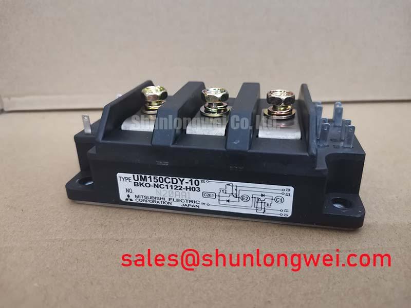
Mitsubishi UM150CDY-10: 500V 150A Single IGBT Module
Introduction to the UM150CDY-10 IGBT Module
Engineered for Simplified Thermal Design and High-Current Switching
The Mitsubishi UM150CDY-10 is a high-performance single IGBT module designed for robust power switching in demanding industrial environments. It delivers reliable performance through a design focused on simplifying thermal management and providing flexibility for power electronics engineers. With core specifications of 500V | 150A | Rth(j-c) 0.16°C/W, this module offers key benefits including simplified thermal design and high power conversion flexibility. The primary advantage of its integrated insulated base is the elimination of external insulating layers, which directly reduces assembly complexity and improves the consistency of heat transfer. For industrial chopper and drive systems on ~240V AC lines prioritizing simplified assembly and thermal reliability, the UM150CDY-10 is an engineered choice.
Application Scenarios & Value
System-Level Benefits in Industrial Power Conversion
The UM150CDY-10 is engineered for a range of high-power switching applications where reliability and efficient thermal performance are critical. Its characteristics make it particularly well-suited for systems where operational robustness and ease of manufacturing are key design drivers.
- Welding Power Supplies: In a high-current welding application, managing intense thermal cycles is a primary engineering challenge. The UM150CDY-10's low thermal resistance (Rth(j-c) of 0.16°C/W) provides an efficient path for heat to escape from the IGBT chip to the heatsink. This capability is crucial for handling the high peak currents of the welding process without exceeding the maximum junction temperature, thus enhancing the equipment's field reliability and lifespan.
- DC Motor Controllers & Choppers: For DC-DC chopper circuits and motor drives, the module's single-switch configuration offers significant design flexibility. Engineers can implement various custom topologies, and the insulated package simplifies the mechanical layout, especially when multiple devices are mounted on a single, common heatsink.
- General-Purpose Inverters: In applications such as uninterruptible power supplies (UPS) and small-scale Variable Frequency Drives (VFDs) operating on 200/240V AC lines, the 500V rating provides an optimal voltage margin without the potential performance trade-offs of a higher-rated 600V device.
For systems requiring operation on higher voltage buses, the related CM200DY-24H provides a 1200V blocking voltage capability.
Key Parameter Overview
Decoding Specifications for Thermal and Electrical Robustness
The technical specifications of the UM150CDY-10 are foundational to its performance in power conversion systems. Below is a summary of key parameters derived directly from the official datasheet. Understanding these values is essential for accurate system modeling and design validation.
| Parameter | Symbol | Conditions | Value |
|---|---|---|---|
| Collector-Emitter Voltage | VCES | VGE = 0V | 500 V |
| Collector Current (DC) | IC | TC = 25°C | 150 A |
| Collector-Emitter Saturation Voltage | VCE(sat) | IC = 150A, VGE = 15V | 2.7 V (Max) |
| Thermal Resistance (Junction to Case) - IGBT | Rth(j-c) | 0.16 °C/W (Max) | |
| Thermal Resistance (Junction to Case) - Diode | Rth(j-c) | 0.3 °C/W (Max) | |
| Isolation Voltage | Viso | AC 1 minute | 2500 Vrms |
| Maximum Junction Temperature | Tj | 150 °C |
Interpreting the Critical Parameters
What is the primary benefit of its insulated base? It simplifies assembly and improves thermal transfer. The Junction-to-Case Thermal Resistance (Rth(j-c)) of 0.16 °C/W is a critical metric for Thermal Management. It quantifies how efficiently heat can be moved from the active silicon die to the module's exterior. Think of it as the width of a highway for heat; a lower number means a wider, multi-lane highway, allowing heat to escape quickly and preventing traffic jams, or thermal buildup, which is a leading cause of semiconductor failure.
The Collector-Emitter Saturation Voltage (VCE(sat)) defines the voltage drop across the IGBT when it is fully turned on. This parameter is a primary contributor to conduction losses. The 2.7V maximum rating at full current is a key input for calculating system efficiency and sizing the required cooling solution.
Technical Deep Dive
The Engineering Advantage of the Insulated Base Design
What is this module's main advantage? It offers robust thermal performance for its class. A standout feature of the UM150CDY-10 is its "Insulated Type" construction. This design integrates a ceramic insulating layer directly into the module's base, which is electrically isolated from the semiconductor terminals. This seemingly simple feature provides significant engineering advantages over traditional non-isolated modules.
Non-isolated modules require a complex thermal stack-up during assembly: the module, a layer of thermal interface material (TIM), a separate ceramic insulator (like alumina), another layer of TIM, and finally the heatsink. Each layer adds thermal resistance and introduces variables in manufacturing, such as mounting pressure and TIM uniformity. The UM150CDY-10's integrated design consolidates this stack. The difference is akin to using a pre-fabricated, factory-sealed window unit versus installing a pane of glass, sealant, and frame as separate components on-site. The integrated solution is simpler to install, more mechanically robust, and provides a more predictable and reliable thermal path from the silicon to the heatsink, ultimately contributing to a lower total cost of ownership.
Frequently Asked Questions
Practical Insights for Design and Implementation
How does the 500V VCES rating of the UM150CDY-10 benefit specific applications?
A 500V rating is well-suited for systems running on 200-240V AC input lines. After rectification, this results in a DC bus voltage of approximately 280-340V. A 500V VCES provides sufficient safety margin to handle voltage spikes from switching or line transients, without being over-specified. Using a device rated for a much higher voltage (e.g., 1200V) in such an application could result in higher conduction and switching losses, leading to lower overall system efficiency.
What are the primary considerations for the gate drive circuit for this IGBT module?
Based on the datasheet, the recommended gate-emitter voltage (VGE) is +15V for turn-on and typically between -5V and -10V for turn-off. A negative turn-off voltage is crucial to provide a strong buffer against parasitic turn-on induced by high dV/dt, enhancing noise immunity. The Gate Drive circuit must be capable of sourcing and sinking sufficient peak current to charge and discharge the IGBT's input capacitance quickly, minimizing switching losses.
Does the isolated base of the UM150CDY-10 eliminate the need for thermal compound?
No. While the isolated base eliminates the need for a separate *insulating pad* (like a mica or ceramic wafer) and one layer of thermal compound, you must still apply a thin, uniform layer of thermal interface material (TIM) between the module's metal baseplate and the heatsink. This compound fills microscopic air gaps to ensure a low-resistance thermal path, which is essential for effective cooling.
Strategic Outlook
The UM150CDY-10 represents a strategic choice for designers of industrial power equipment. Its focus on integrated isolation directly addresses the industry's need for more streamlined manufacturing processes and enhanced long-term field reliability. By reducing component count and simplifying the thermal interface, this Mitsubishi IGBT module helps lower the total cost of ownership, a critical metric in competitive industrial markets. Investing in components that simplify design and enhance robustness is a forward-looking strategy for developing durable and cost-effective power systems.