


Content last revised on April 15, 2026
Fuji Electric 7MBR15SA140-50: A 7-in-1 Power Integrated Module Engineered for Compact Motor Drives
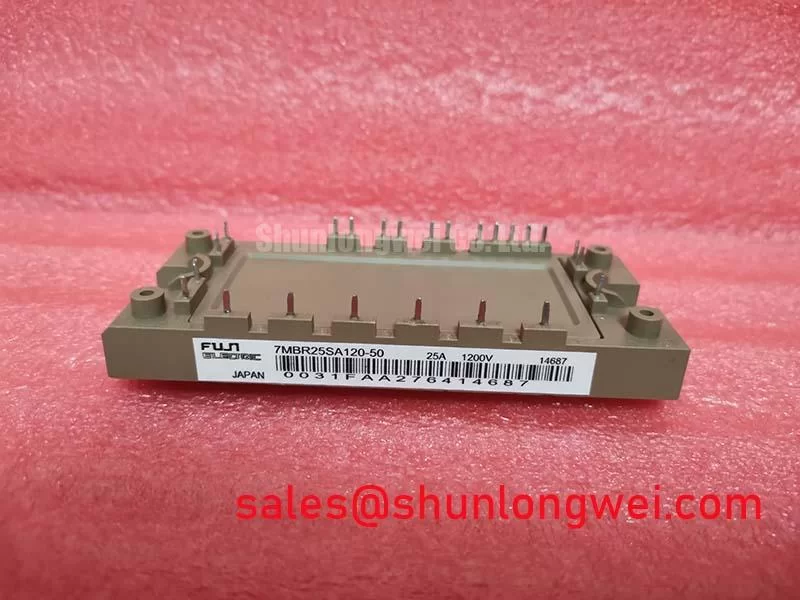
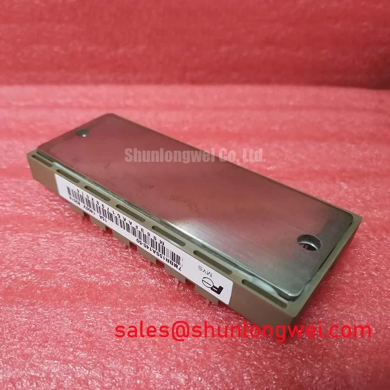
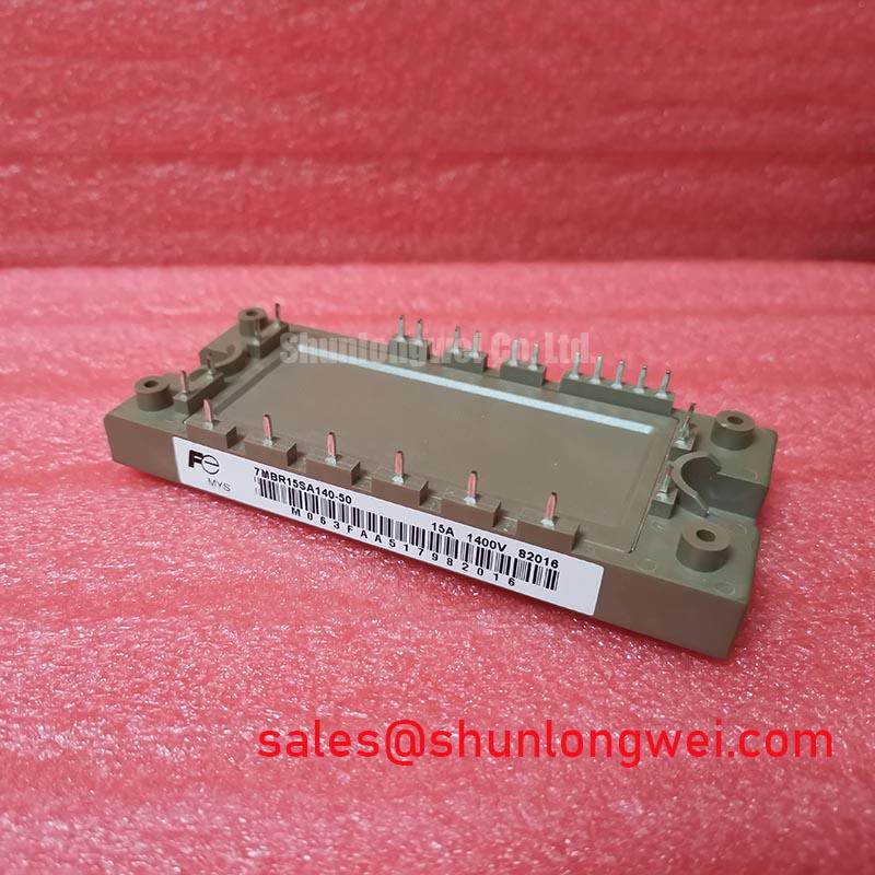
The 7MBR15SA140-50 from Fuji Electric is a highly integrated Power Integrated Module (PIM) designed to streamline the power stage of low-power motor drives and uninterruptible power supplies. This module offers a robust 7-in-1 configuration, combining a three-phase converter bridge, a brake chopper, and a three-phase inverter into a single, compact package. Its 1400V collector-emitter voltage provides a substantial safety margin for systems operating on 400V to 480V AC lines, while the 15A current rating is tailored for fractional to low horsepower applications. Key benefits include simplified PCB layout, reduced assembly complexity, and enhanced thermal performance due to its integrated nature. This module directly addresses the engineering challenge of designing cost-effective, space-constrained, and reliable power conversion systems. For applications requiring higher current handling while maintaining a similar integrated topology, the related 7MBR25SA120-50 offers a 25A capability.
Key Parameter Overview
Decoding the Specs for Integrated Drive Design
The specifications of the 7MBR15SA140-50 are optimized for efficiency and reliability in compact power systems. The parameters below highlight its suitability for applications where thermal management and electrical ruggedness are primary design considerations.
| Parameter | Symbol | Condition | Value |
|---|---|---|---|
| Inverter Section (per IGBT) | |||
| Collector-Emitter Voltage | VCES | - | 1400V |
| Continuous Collector Current | IC | TC = 25°C | 15A |
| Collector-Emitter Saturation Voltage | VCE(sat) | IC = 15A, VGE = 15V | 2.7V (Typ) |
| Thermal Resistance (Junction-to-Case) | Rth(j-c) | Per IGBT | 1.14 °C/W |
| Brake Section (IGBT) | |||
| Collector-Emitter Voltage | VCES | - | 1400V |
| Continuous Collector Current | IC | TC = 25°C | 15A |
| Collector-Emitter Saturation Voltage | VCE(sat) | IC = 15A, VGE = 15V | 2.7V (Typ) |
| Converter Section (per Diode) | |||
| Repetitive Peak Reverse Voltage | VRRM | - | 1600V |
| Forward Voltage | VF | IF = 15A | 1.5V (Typ) |
Download the 7MBR15SA140-50 datasheet for detailed specifications and performance curves.
Application Scenarios & Value
Streamlining Low-Power AC Servo and VFD Systems
The 7MBR15SA140-50 is an excellent fit for compact, low-power industrial automation systems. A primary engineering challenge in small Variable Frequency Drives (VFDs) or AC servo amplifiers is maximizing power density while minimizing assembly costs and ensuring thermal stability. This module's high level of integration is its core value proposition. By combining the input rectifier, brake chopper for managing regenerative energy, and the final inverter stage into one component, it dramatically simplifies the power stage design. This reduces the PCB footprint, lowers the bill of materials (BOM), and decreases the number of manufacturing steps.
Consider the design of a servo drive for a packaging machine. The drive must respond quickly to commands, which involves rapid acceleration and deceleration cycles. During deceleration, the motor acts as a generator, creating regenerative energy that must be dissipated to prevent DC bus overvoltage. The 7MBR15SA140-50's integrated brake circuit provides a ready-made solution, simplifying the implementation of dynamic braking. The module's thermal resistance (Rth(j-c)) of 1.14 °C/W per IGBT is a critical parameter. This value dictates how efficiently heat is transferred from the silicon chip to the heatsink. A lower thermal resistance allows for a smaller, more cost-effective cooling solution, which is essential for maintaining a compact overall system size. Its high VCES of 1400V provides a significant safety margin against voltage spikes on industrial power lines, enhancing the long-term reliability of the servo drive. What is the primary benefit of its 7-in-1 integration? A significant reduction in system complexity and assembly time.
Technical Deep Dive
The Engineering Impact of High Integration and Thermal Design
The design of the 7MBR15SA140-50 reflects a strategic choice to prioritize system-level simplification over discrete component performance. While individual discrete IGBTs might offer slightly lower VCE(sat), the value of this module lies in its pre-engineered, thermally matched, and electrically isolated construction. The integration of seven power devices into a single package solves multiple engineering problems simultaneously.
Firstly, it mitigates issues related to parasitic inductance and capacitance between power stages. In a discrete design, the physical layout of the rectifier, brake, and inverter can create stray inductances that lead to voltage overshoots and electromagnetic interference (EMI). By placing all components within a compact module, these interconnects are minimized and optimized, leading to cleaner switching and simplifying EMI filter design. Secondly, the module simplifies thermal management. Instead of managing the heat from multiple separate components, engineers can focus on cooling a single, well-characterized thermal interface. This is akin to managing the cooling for a single multi-core CPU rather than several individual processors; the heat source is centralized, allowing for a more efficient and predictable cooling strategy. The shared substrate ensures a degree of thermal coupling between the components, which can be beneficial in applications with intermittent brake usage, allowing for more uniform heat distribution across the module's baseplate.
Frequently Asked Questions (FAQ)
What is the primary advantage of the 1400V VCES rating for a 400V system?
The 1400V rating provides a substantial safety margin, protecting the IGBTs from transient overvoltages that are common in industrial environments. This ruggedness is crucial for ensuring reliability in applications like motor drives, where switching actions and line fluctuations can cause significant voltage spikes.
How does the integrated brake chopper in the 7MBR15SA140-50 simplify system design?
The integrated brake chopper eliminates the need for a separate braking IGBT and its associated gate drive circuitry. This simplifies the PCB layout, reduces component count, and lowers assembly costs. It provides a built-in solution for managing the regenerative energy from a decelerating motor, which is a common requirement in servo and VFD applications, preventing DC bus overvoltage faults.
System-Level Benefits
For engineering teams developing compact motor drives, AC servo amplifiers, and small uninterruptible power supplies, the 7MBR15SA140-50 offers a compelling path to a smaller, more reliable, and cost-effective design. Its high level of integration reduces not only the component count but also the design and validation time associated with laying out and thermally managing a discrete power stage. This module allows designers to focus on higher-level control and software features, accelerating the time-to-market. For a deeper understanding of IGBT selection, explore our guide on Decoding IGBT Datasheets: A Practical Guide for Engineers.