Content last revised on September 11, 2026
6MBI150UB-120-02 Operational Boundaries: Evaluating Regenerative DC Bus Voltage Surge Dissipation
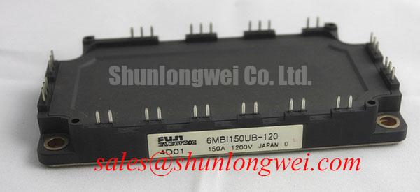
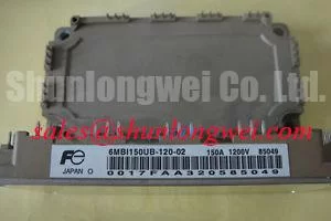
The 6MBI150UB-120-02 is a Fuji Electric IGBT module with a specified voltage rating of 1200 V and a rated current of 150 A, supplied in a module package. A 20.0 V value associated with this device refers to the gate-emitter voltage rating rather than the main power-voltage rating. These values should be treated as Official Specification data for identification and procurement comparison. The system integrator should verify every operating voltage, terminal assignment, switching condition, and protection threshold against the original Fuji Electric documentation and the equipment schematic before installation.
In regenerative drive sections, motor deceleration can return energy to the DC bus. A braking IGBT path and ballast resistor are commonly assessed as a system level energy handling arrangement, not as an inherent function confirmed for this specific module. Design Consideration: inspect the braking resistor circuit, associated wiring, resistor thermal condition, and suppression network before attributing a DC bus alarm to the power module. A failed resistor connection, degraded contactor, open fuse, or incorrectly timed control signal can each contribute to a rising bus voltage.
For inverter welders and medium frequency induction heating supplies, service personnel should capture bus voltage behavior during controlled start, load removal, and shutdown events. Compare the waveform with a known good unit where available. Peak voltage, switching ringing, and braking activation timing must be evaluated at the complete converter level because cable routing, DC link capacitance, load inertia, and control firmware all affect the observed result.
Keep high energy conductors physically organized and separated from low level gate command wiring. Design Consideration: minimize the commutation loop area to reduce inductive overshoot during switching, then verify peak voltage margins through properly rated measurement equipment. For topology comparison, the 2MBI150UC-120 is a related module reference that engineers may review when mapping the rectifier or complementary power stage in an existing assembly.
Preventing Spurious Faults: Managing Reflected Voltage on 6MBI150UB-120-02 Motor Connections
Long motor cables can create impedance discontinuities that reflect switching transitions back toward inverter terminals. This can produce a measured terminal waveform substantially different from the DC bus waveform. It should not be assumed that one observed spike identifies a single defective part. Check the probe connection method, probe bandwidth, motor cable routing, output reactor condition, filter connections, and grounding arrangement before changing the power assembly.
When an output filter or choke is fitted, confirm that its wiring follows the original machine layout and that its terminals have not loosened from thermal cycling. Design Consideration: output filtering is selected to manage switching edge behavior and motor cable interactions under the actual cable length, switching frequency, load current, and controller settings. The final filter selection belongs to the system designer and should be verified by switching tests against the applicable DC link and device limits.
Thermal mounting quality also affects fault repeatability. A clean, flat heatsink interface and an even thermal interface material layer are important for stable heat transfer. A 50 to 80 μm thermal interface material thickness is a General Industry Design Consideration where the material supplier and equipment design support that range; it is not an official Fuji Electric requirement for this model. Tighten mounting hardware in a cross pattern using the fastening sequence and torque specified by the equipment manufacturer or applicable module documentation.
⚡ Bench Tip: Discharge the DC link, use ESD controlled handling, and record cold state diode mode readings before and after mounting so that later checks have a valid baseline.
Inspect the module mounting face, heatsink flatness, busbar contact surfaces, and nearby snubber or MOV components for heat discoloration or mechanical stress. A MOV can be part of a coordinated overvoltage suppression network, but its clamping behavior, energy capability, and placement must be evaluated within the complete system rather than inferred from the module part number. For a higher current reference within the same product family, engineers can compare documented interface and rating differences with 6MBI300U-120 without assuming interchangeability.
6MBI150UB-120-02 Circuit Protection and Reliability: Isolation Path Checks for Gate Commands
Before applying gate drive power, verify that the driver board isolation barrier, control supply return path, and gate command routing match the machine schematic. Optocouplers and digital isolators are different isolation technologies, and neither should be regarded as interchangeable solely because both can transfer a switching command. The selected component must satisfy the system isolation requirement, switching timing requirement, and common mode transient conditions established by the equipment designer.
Design Consideration: unwanted gate activity can arise from return path inductance, an incorrectly referenced probe, damaged isolation components, control supply instability, or conducted noise coupling into the gate loop. A bench check should begin with the inverter disabled, then progress through isolated gate supply verification, command signal observation, and controlled switching tests. Capture gate emitter behavior and power terminal behavior using measurement practices appropriate to the voltage present.
Maintain practical clearance between high voltage power conductors and low voltage control wiring, especially where busbars pass near driver boards or connector harnesses. Check for trapped wires, loose shielding terminations, contamination, and conductive debris. The module package itself does not establish system EMC compliance or equipment safety certification. Those outcomes depend on enclosure design, cabling, grounding, filter implementation, and verification of the complete machine.
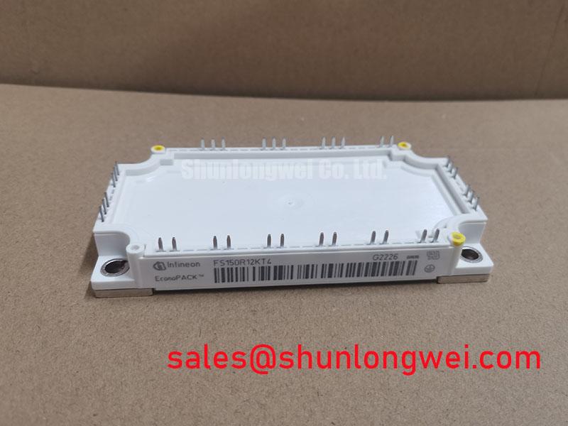
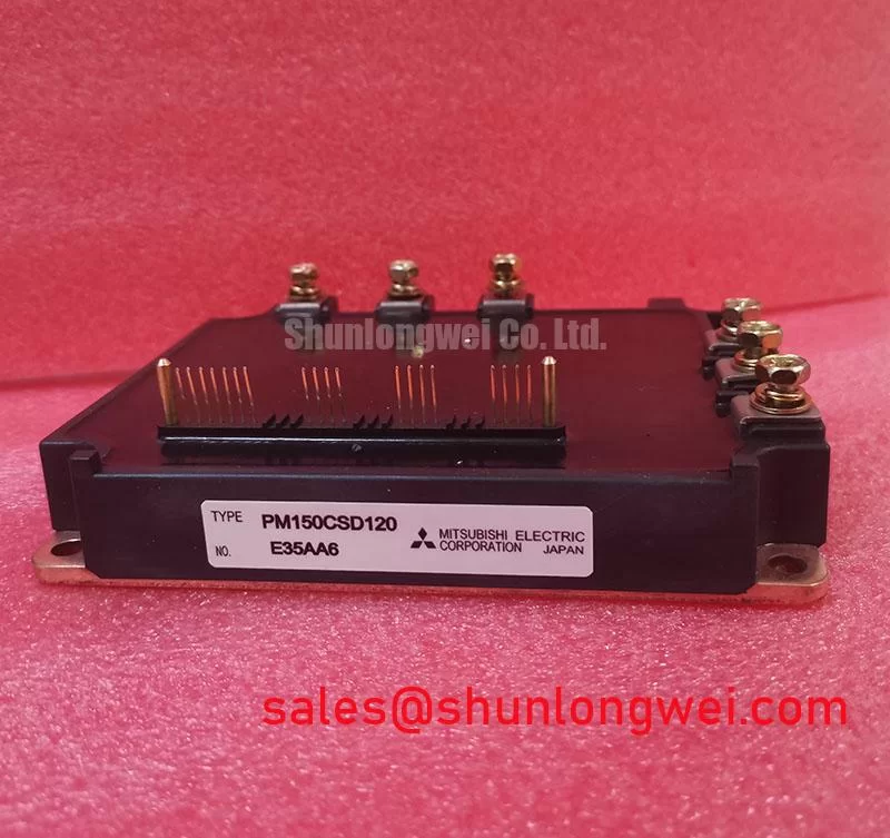
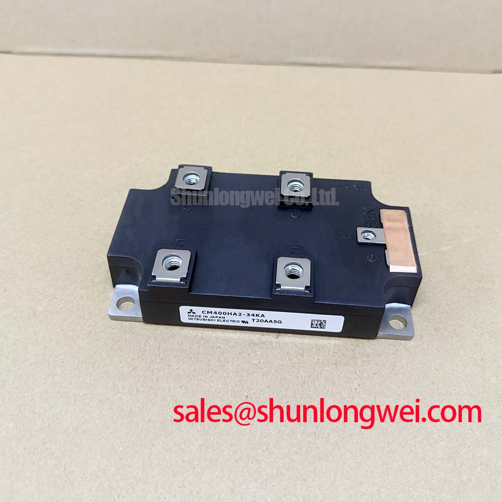
Fuji Electric publishes broader product family information for brake chopper IGBT modules and RC IGBT modules. These references can help engineers distinguish power stage functions, but they do not replace the original documentation for the 6MBI150UB-120-02.
For gate loop layout principles, isolated command routing, and measurement focused commissioning practices, see Precision Gate Drive Design. Apply any design principle only after confirming the actual device ratings, driver circuit, and waveform conditions in the equipment under repair.
Field Diagnostics and Commissioning: Environmental Assessment of 6MBI150UB-120-02 Topologies
During commissioning, inspect the module enclosure, terminal hardware, heatsink interface, control connectors, and surrounding suppression components before energizing the converter. Confirm that the installed module marking matches the service record and that the original equipment documentation supports its use in the intended circuit position. Because the specified device voltage rating is 1200 V and its rated current is 150 A, operation near these limits requires documented verification of the complete application before power is applied.
Environmental factors such as altitude, contamination, humidity, vibration, cooling air quality, and thermal cycling can influence converter behavior. No field failure rate, service life value, single event burnout rate, or altitude derating value is asserted here because such values require applicable manufacturer data or a cited qualification source. Design Consideration: where a system operates at elevated altitude or in an electrically noisy enclosure, review the original system insulation coordination, cooling arrangement, DC bus operating conditions, and protection response with qualified engineering personnel.
A practical diagnostic sequence is to inspect the unpowered assembly, confirm the gate driver supply and command state, verify busbar and heatsink connections, and then observe controlled low risk operating conditions using suitable instruments. If waveforms differ from the known good signal path, investigate cable impedance, grounding, gate driver isolation, suppression components, and mechanical connections together. This approach preserves evidence and avoids treating a single meter reading as proof of a single failure mechanism.