

Content last revised on September 26, 2026
Field Diagnostics and Commissioning: Checking the SPE24-8R4 Supply in a Switching System
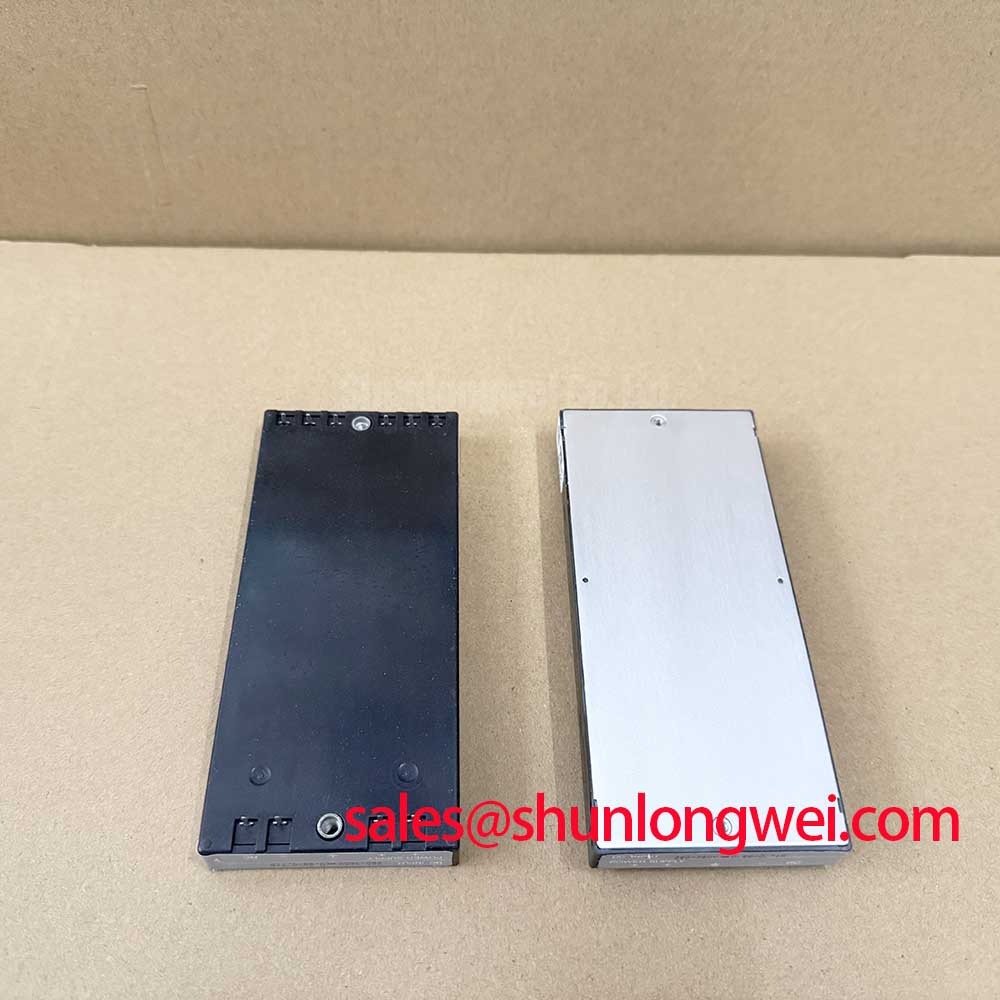
With the control board de-energized, compare the fitted converter’s marking and connector wiring with the service documentation before checking whether the board supplies the 24 V DC nominal input required by the SPE24-8R4. P-Duke Power specifies an asymmetric first output of +15 V DC, a maximum output power of 2 W, and typical efficiency of 75%–81% (Official Specifications). Those figures establish the starting point for evaluating this DC-DC converter; the original equipment documentation must establish the complete pinout, remaining output requirements, and permissible operating conditions.
Start at the converter rather than at the power switch. On an unpowered board, inspect its solder joints, surrounding components, and connector seating. Automated optical inspection is one established way to examine assembly features, but bench inspection remains useful when tracing a service fault; the principles of automated optical inspection do not, by themselves, establish electrical fitness. Check the input path for an unintended short, then confirm input polarity against the equipment schematic before applying power.
During commissioning, measure the voltage at the converter’s input terminals while the intended load is connected. A nominal 24 V DC source at the upstream supply does not prove that the same voltage reaches the converter during a transient. Measure the +15 V DC first output at its load and observe startup and shutdown with an appropriately rated instrument. If the rail dips when the inverter begins switching, compare input and output waveforms against a known-good board and check connectors, upstream regulation, and load behavior before assigning the fault to the converter.
Design Consideration: In an industrial inverter welder or medium-frequency induction heating supply, keep the converter’s low-power input and output routing distinct from the high-current commutation loop. Stray inductance in that loop can contribute to switch turn-off overshoot, but its allowable value and any snubber selection depend on the complete power stage and measured switching waveforms, not on the SPE24-8R4 rating. The Industrial Applications reference provides broader power-stage context; it is not a substitute for checking this converter’s own electrical limits.
SPE24-8R4 Circuit Protection and Reliability: Separating Converter Limits From Power-Stage Hardware
The 2 W maximum output power is an Official Specification for the SPE24-8R4. When reviewing a replacement or revised control board, account for every load connected to its outputs using the original wiring diagram. The stated 75%–81% typical efficiency describes conversion performance; it is not a guaranteed operating-temperature rating or a basis for assuming that enclosure cooling is adequate. Verify the permitted ambient conditions and any required derating in the applicable manufacturer documentation before approving installation.
Thermal-interface thickness, baseplate flatness, mounting-screw sequence, and semiconductor fuse coordination belong to the associated power module and heatsink assembly. They are not SPE24-8R4 specifications. Design Consideration: If the same repair involves that assembly, follow its own mounting and surge-rating documentation, then verify fuse coordination against the actual fault path. Applying a power-module mounting procedure to a board-mounted DC-DC converter would obscure the separate checks each part needs.
For the converter circuit, trace the input protection components and output loads on the equipment schematic. Look for a stressed upstream suppressor, a damaged connection, or an abnormal load before replacing the converter solely because its output is absent. Disconnect power and verify that stored energy has discharged before unplugging the control board. An absence of output is a measurement result, not a single-cause diagnosis.
Preventing Spurious Faults: Long-Lead Switching Noise and the SPE24-8R4 Control Rail
Long motor or work-coil connections can complicate an inverter system’s switching behavior, but reflected-wave voltage is a property of the power circuit, cable, and load. It is not an output characteristic of the SPE24-8R4. If control faults coincide with switching events, probe the converter input and the +15 V DC first output at the board, while separately measuring the power-stage waveform with equipment suitable for its voltage and common-mode environment. Correlation can guide further testing; it does not establish that a cable reflection has damaged the converter.
Design Consideration: Evaluate cable routing, bonding, filtering, and any output choke or dv/dt filter as parts of the complete machine. Their selection should follow measured terminal waveforms and the ratings of the connected drive and load. Electromagnetic shielding explains a useful coupling-control principle, but shielding a cable or enclosure does not certify the converter or the assembled machine for EMC compliance.
If a replacement board behaves differently, document where each measurement was taken and whether the intended load was present. A stable unloaded reading does not demonstrate adequate performance under the equipment’s operating load. Confirm the complete output configuration and permitted loading from the original P-Duke Power documentation rather than inferring them from the first-output voltage alone.
Assembly Integrity and Layout: Supporting Gate-Drive Control Without Misidentifying the Converter
The SPE24-8R4 is a DC-DC converter, not an IGBT switch or an active Miller-clamp circuit. Gate-drive dead time, Miller-effect suppression, and cross-conduction protection must be assessed in the driver and power-stage design. If the converter supplies part of that circuitry, identify exactly which rails and returns it serves on the equipment schematic. Do not assume that its specified +15 V DC first output establishes a negative gate-bias rail, an isolation rating, or a particular protection response.
💡 Pro Tip: When investigating switching-related control resets, compare the converter rail and the gate-driver input at the same operating event, then review return-path routing and power-loop geometry before changing protection components. This is an Engineering Recommendation for fault isolation, not a prescribed layout dimension. Driver timing and peak-voltage margins still require validation on the assembled system under representative switching conditions.
For cross-model sourcing, compare function before comparing part numbers. SKIIP37AC12T4V1 is a power-module listing, not a stated electrical substitute for the SPE24-8R4 converter. An SPE24-8R4 replacement assessment should instead verify the original converter documentation, footprint, pin assignments, input conditions, all output loads, and the control board’s startup behavior.