Content last revised on September 10, 2026
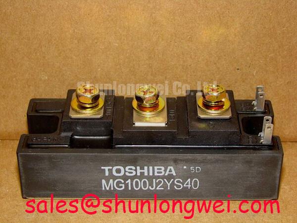
Toshiba MG100J2YS40 Dual IGBT Module: Precision Power Control for 600V Industrial Systems
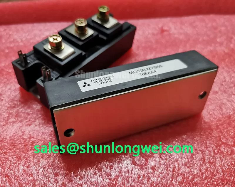
The Toshiba MG100J2YS40 is a high-performance Silicon N-Channel IGBT module designed for high-speed switching and efficient power conversion in industrial environments. Featuring a dual-unit (half-bridge) configuration, this module provides 600V collector-emitter voltage and 100A collector current handling, making it a staple for engineers designing robust inverter and drive stages. By integrating low saturation voltage with optimized switching characteristics, it significantly reduces thermal overhead in high-duty cycle applications. What is the primary benefit of its low saturation voltage? It minimizes conduction losses to enhance system efficiency and reduce cooling requirements. For motor drives requiring a balance of 600V protection and 100A throughput, the MG100J2YS40 is the preferred industrial choice.
Key Parameter Overview
Decoding the Specs for Enhanced Thermal Reliability
The following technical specifications represent the absolute maximum ratings and typical electrical characteristics derived from the official Toshiba engineering documentation. These values are critical for defining the safe operating area (SOA) during the design phase of power electronic converters.
| Characteristic | Symbol | Rating / Value (Typical) |
|---|---|---|
| Collector-Emitter Voltage | Vces | 600V |
| Gate-Emitter Voltage | Vges | +/- 20V |
| Collector Current (DC) | Ic | 100A |
| Collector Power Dissipation (Tc=25°C) | Pc | 400W |
| Collector-Emitter Saturation Voltage | Vce(sat) | 2.7V (at Ic=100A) |
| Fall Time (Switching) | tf | 0.5µs |
| Isolation Voltage | Visol | 2500V AC (1 min) |
Application Scenarios & Value
Achieving System-Level Benefits in High-Frequency Power Conversion
Engineers often face the challenge of managing heat in compact enclosures while maintaining high output current. The MG100J2YS40 addresses this by utilizing a high-speed IGBT chip that minimizes switching losses (Eon/Eoff). In Variable Frequency Drive (VFD) applications, where the switching frequency typically ranges from 2kHz to 15kHz, the 0.5µs fall time ensures a clean transition, reducing the EMI footprint and the stress on the gate drive circuitry.
For systems involving Uninterruptible Power Supplies (UPS), the module’s 2500V AC isolation rating ensures that the power stage remains safely separated from the control logic, meeting stringent safety standards. In scenarios requiring even higher current handling within the same voltage class, the MG150Q2YS50 offers a higher collector current of 150A, providing a modular upgrade path for existing chassis designs. This compatibility simplifies System Integration & Design Simplification across a product lineup.
Understanding the interplay between voltage and current is essential for long-term reliability. To further explore these concepts, refer to our In-depth Analysis of IGBT Modules and our guide on Preventing Overtemperature Failures.
Technical Deep Dive
Analyzing Switching Efficiency and Loss Reduction Strategies
The MG100J2YS40 utilizes an N-channel enhancement mode structure that excels in VCE(sat) control. To visualize this, consider VCE(sat) as the "internal resistance" of a valve; the lower it is, the less pressure (energy) is lost as water (current) passes through. At 2.7V, the conduction losses are tightly controlled even at the peak 100A current. This efficiency is critical for Thermal Management because every watt saved in conduction translates to a smaller, more cost-effective heatsink design.
The high-speed switching capability is achieved through an optimized gate structure that reduces parasitic capacitance. This allows for faster charging and discharging of the gate-emitter junction, directly influencing the Short-Circuit Withstand Time and the module's ability to handle inductive loads in motor drives. When performing field maintenance, knowing how to test an IGBT module with a multimeter is vital for verifying that the gate oxide remains intact after high-stress operation.
Frequently Asked Questions
How does the Vce(sat) of 2.7V directly impact the cooling requirements for the MG100J2YS40?
The saturation voltage determines the conduction loss (P = Vce(sat) x Ic x Duty Cycle). A typical 2.7V at 100A results in 270W of peak instantaneous heat. Lower saturation voltage directly reduces the total thermal energy the heatsink must dissipate, allowing for higher power density or lower operating temperatures.
What is the significance of the 0.5µs fall time in high-frequency inverter designs?
The fall time represents how quickly the IGBT stops conducting current. A shorter fall time, like the 0.5µs found in the MG100J2YS40, reduces the overlap between decreasing current and increasing voltage during the turn-off phase. This reduction in overlap significantly lowers switching losses, which is paramount for high-frequency operation.
Is the isolation voltage of the MG100J2YS40 sufficient for 480V three-phase systems?
Yes. The MG100J2YS40 is rated for 2500V AC isolation for one minute. In a standard 480V system, the peak line voltage is approximately 680V. The 2500V rating provides a substantial safety margin, ensuring that transient voltage spikes do not breach the dielectric barrier between the power terminals and the baseplate.