
Content last revised on September 10, 2026
Preventing Spurious Faults: Differential Gate-Emitter Loop Routing Guidelines for 6MBI150UB-120
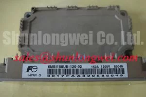
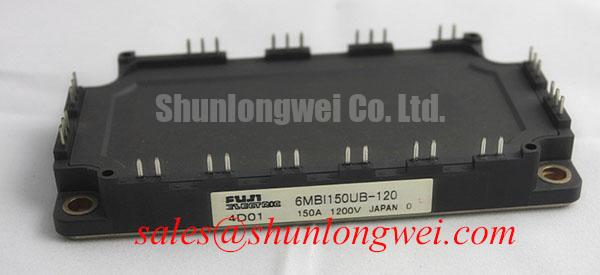
The Fuji Electric 6MBI150UB-120 IGBT module is rated at 1200 V collector-emitter voltage and a 150 A rated collector current at a case temperature of 80°C, according to the official datasheet specifications. Its typical collector-emitter saturation voltage is 2.10 V, typical turn-off switching loss is 17.5 mJ, short-circuit withstand time is 10 µs at 800 V, and IGBT junction-to-case thermal resistance is 0.13°C/W. These values provide a factual starting point for assessing an existing industrial inverter, including traction controllers, material handling drives, and heavy-duty motor control cabinets.
| Official Parameter | Specified Value | Integration Relevance |
|---|---|---|
| Collector-emitter voltage | 1200 V | Voltage rating for inverter DC link and switching transient assessment |
| Rated collector current | 150 A at Tc = 80°C | Current capability under the stated case temperature condition |
| Collector-emitter saturation voltage | 2.10 V typical | Reference value for conduction loss evaluation |
| Turn-off switching loss | 17.5 mJ typical | Reference value for thermal estimation at the applied switching conditions |
| Short-circuit withstand time | 10 µs at 800 V | Protection circuit response must be validated within the applicable fault window |
| IGBT junction-to-case thermal resistance | 0.13°C/W | Supports thermal path calculation from semiconductor junction to baseplate |
Spurious overcurrent trips, irregular gate waveforms, and intermittent drive shutdowns should be investigated at the gate return path before changing protection thresholds. The power emitter path carries substantial switching current and develops voltage across unavoidable stray inductance. If the gate driver reference shares that noisy path, the driver can see an apparent gate-emitter voltage that differs from the voltage intended by the control circuit. That condition can alter switching timing, create ringing, or cause an otherwise healthy controller to report a fault.
Design Consideration: route each gate signal and its dedicated low-current return as a closely coupled pair from the driver to the module control terminals. Keep this loop physically separate from the main collector and emitter current loop wherever the module terminal arrangement allows it. If the module and driver assembly provide a dedicated auxiliary emitter or sensing return, it should be used only as the gate driver reference rather than as a path for load current. The original Fuji Electric module documentation and the existing inverter schematic should be checked before assigning any terminal function.
For a repair bench, compare gate-emitter waveforms at the module terminals rather than only at the driver board connector. A waveform that appears clean at the controller may show oscillation after cable impedance, connector resistance, or a poorly routed return path is included. Measure each switching position under controlled load and compare turn-on and turn-off behavior across the installed channels. A difference can indicate asymmetric gate wiring, connector condition, driver supply disturbance, or local parasitic coupling. It does not by itself prove a failed IGBT.
Gate leads should not run alongside high-current busbars for extended distances. Where a controller uses a ribbon cable or separate harness between gate board and power stage, inspect strain relief and connector retention as part of preventive maintenance. Vibration in electric material handling equipment can gradually change contact resistance at low-current terminals long before a visible fault appears at the power terminals.
⚠️ Maintenance Note: Isolate and discharge the DC link before reconnecting gate or power wiring, then monitor terminal contact temperature and confirm that cooling air passages remain clear during the return to service.
For product family comparisons, the 2MBI150UC-120 can be reviewed as a separate Fuji Electric module reference, but electrical topology, terminal assignment, thermal interface, and gate drive requirements must be verified against the original equipment documentation before any replacement decision.
6MBI150UB-120 Circuit Protection & Reliability: Calibrating Thermal Feedback
The typical 2.10 V VCE(sat) specification is useful for conduction loss estimation, but it is not a fixed field measurement threshold for pass or fail diagnosis. VCE(sat) changes with collector current, junction temperature, gate drive conditions, and the test conditions defined by the manufacturer. In parallel current paths, the positive temperature coefficient of IGBT saturation behavior can support steady-state current sharing under appropriate operating conditions. Dynamic sharing remains dependent on balanced gate loop resistance, similar physical routing, matched driver timing, and symmetric power connections.
Design Consideration: maintain a compact laminated or closely coupled DC bus structure around the switching loop to reduce parasitic inductance. During turn-off, loop inductance combines with changing current to produce a voltage overshoot. The system engineer should verify measured collector-emitter peak voltage against the DC link and the 1200 V module rating under actual load, temperature, and switching conditions. A short, direct connection between the DC link film capacitor and the power stage is generally valuable because it reduces the high-frequency current loop area.
Snubber film capacitors, where present in the original inverter design, should remain close to the switching power terminals and be examined for terminal integrity and heat exposure. Their capacitance and equivalent series resistance should be assessed using suitable test equipment if repeated transient alarms occur. An MOV-based surge suppression network can address externally introduced surge energy, while a local film capacitor and properly arranged busbar address switching loop energy. These functions are complementary, not interchangeable. MOV selection and coordination with fuses, contactors, and DC link capacitors are system-determined and should be verified against the complete protection architecture.
In battery-powered traction equipment, bidirectional DC-to-DC charging and regenerative operation can impose recurring thermal cycles on the inverter assembly. The module data supplied here identifies its electrical and thermal ratings, but it does not establish a vehicle service life or a maintenance interval. Engineering Recommendation: trend heat sink cleanliness, fan performance where used, DC link connection condition, and drive fault history. Check for moisture ingress or condensation after large temperature changes because surface contamination can compromise low-energy signal paths even when the power stage appears normal.
The broader power module portfolio can be viewed through Fuji Electric Power Semiconductor and IPM Modules. When reviewing the upstream or complementary power section of a cabinet, engineers may also compare the documented characteristics of the 6MBI300U-120. This is an adjacent technical reference rather than a statement of interchangeability.
Benchtop Waveform Tuning: Mitigating Stress via Junction-to-Case Thermal Network Simulation on 6MBI150UB-120
Thermal evaluation begins with the mechanical interface, not with a simulated junction temperature. Clean the heatsink mounting surface, inspect the module baseplate for handling damage, and remove old thermal material without scratching either contact face. A thin, uniform thermal interface material layer is a Design Consideration intended to fill microscopic surface variation while avoiding excess material that increases thermal resistance. The required material, application method, and mounting torque should follow the original equipment procedure or the applicable module mounting documentation.
The official 0.13°C/W junction-to-case thermal resistance for the IGBT describes one portion of the heat path. The final temperature rise also depends on switching losses, conduction losses, thermal interface performance, heatsink resistance, airflow, enclosure temperature, and load duty cycle. For pulsed overload assessment, a transient thermal model with multiple resistance-capacitance sections is preferable to applying only the steady-state resistance. Engineering Calculation can combine measured or estimated loss energy over the load interval with the manufacturer-supplied thermal impedance curve when that curve and operating conditions are available.
On a controlled bench, begin with the original gate drive and protection settings wherever possible. Capture collector-emitter voltage, collector current, gate-emitter voltage, DC link voltage, and heatsink temperature together. Check whether overshoot and ringing change as current increases or as the power stage reaches normal operating temperature. A thermal symptom that follows time at load can arise from inadequate heatsink contact, restricted airflow, deteriorated interface material, unequal current sharing, or changing driver behavior. The evidence from synchronized measurements is more useful than assigning a single cause from one waveform.
For maintenance planning, inspect the heatsink fins and fan inlet path during scheduled shutdowns. Dust accumulation can reduce airflow and raise case temperature without producing an immediate alarm. Verify that mounting hardware remains secure after vibration exposure and that no conductive debris has accumulated around the module terminals. For a broader discussion of thermal path development and cooling architecture, see The Advanced Thermal Management Revolution.
When a replacement module is installed, retain baseline commissioning records. A set of reference waveforms at known battery voltage, ambient condition, and representative load gives later maintenance teams a practical comparison point. It also helps distinguish a progressive system-level change from a sudden assembly issue after a service event.
Transient Dynamics & Electrical Design: High-Frequency Common-Mode Bearing Current on 6MBI150UB-120
Long motor cables can turn a traction inverter output into a transmission-line environment. Fast switching edges launched from the module can reflect at the motor terminals when cable and motor impedance are mismatched. Under some cable and load conditions, reflected voltage can approach twice the DC-link-related step at the motor end. This is a system-level behavior, not an official voltage specification of the 6MBI150UB-120, and it must be measured on the actual cable and motor arrangement.
Common-mode voltage can also couple through motor capacitance, bearings, cable shields, chassis paths, and sensor wiring. Bearing current concerns should be evaluated as part of the complete motor drive installation, including cable routing, grounding architecture, motor construction, and output filter arrangement. Engineering Recommendation: use differential probes with suitable bandwidth and isolation when measuring inverter output transients, and establish probe placement that does not create an unintended measurement loop.
Where transient measurements show excessive motor terminal stress or interference with encoder and control signals, the system integrator should evaluate an output reactor, sine filter, dv/dt filter, shield termination strategy, or other manufacturer-approved mitigation. Filter selection depends on motor cable length, PWM operating conditions, leakage current limits, motor insulation capability, control behavior, and thermal capacity. It should be validated in the final equipment rather than selected from an assumed universal value.
For equipment maintenance personnel, inspect the output cable for crushed insulation, poor shield termination, moisture entry, and loose motor terminal hardware. These conditions may alter cable impedance or grounding continuity and can complicate waveform behavior. Electrostatic handling measures should also protect exposed control boards and gate driver electronics during service. The relevant test framework is described by IEC 61000-4-2 Electrostatic Discharge Immunity, while compliance of the finished machine remains a system-level responsibility.
The 1200 V, 150 A, and stated thermal characteristics of this Fuji Electric module give maintenance and design teams clear boundaries for equipment assessment. Correct gate return routing, controlled switching loop geometry, verified thermal contact, and measured cable-side transients help keep those published limits meaningful in operating equipment.