
Content last revised on September 10, 2026
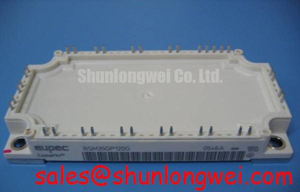
BSM35GP120G Infineon 1200V 35A EconoPIM™ 2 IGBT Module
How can power electronics engineers reduce board footprint and assembly complexity in 400V industrial motor drives without sacrificing thermal headroom? The BSM35GP120G engineered by Infineon (Eupec) addresses this exact challenge by combining a complete Converter-Inverter-Brake (CIB) topology into a single package.
The BSM35GP120G is a high-density Power Integrated Module (PIM) featuring a 1200V breakdown voltage and a 35A collector current rating housed in an industry-standard EconoPIM™ 2 enclosure. By incorporating a three-phase input rectifier, a six-pack inverter stage, an integrated brake chopper transistor, and an NTC temperature sensor, it simplifies system-level PCB layout. Key technical highlights include a typical 2.4V collector-emitter saturation voltage (VCE(sat)) and robust short-circuit capability.
- System Simplification: Consolidates 10 power semiconductors and temperature sensing into one module.
- Thermal Efficiency: Low thermal resistance substrate ensures reliable operation under cyclic industrial loads.
What is the key structural benefit of a PIM module like the BSM35GP120G? It integrates rectifier, inverter, brake chopper, and NTC into a single substrate. For 400V AC three-phase industrial motor drives requiring compact packaging, the BSM35GP120G PIM topology delivers an ideal balance of power density and reliability.
Engineering FAQ
Resolving Thermal and Integration Questions for Power Stage Layout
How does the integrated NTC thermistor in the BSM35GP120G improve system-level protection?
How does the integrated NTC thermistor enhance system reliability? It enables direct, real-time substrate temperature monitoring for over-temperature protection. Placing the sensor directly on the insulated metal substrate minimizes thermal latency compared to external heatsink sensors, enabling gate drivers to respond rapidly to over-temperature conditions before silicon junction limits are breached.
What design parameters govern the selection of the brake chopper gate resistor in this module?
The internal brake chopper switch handles transient energy dump during motor deceleration. Designers must select the external gate resistor (RG,br) to balance switching losses against overvoltage spikes caused by parasitic loop inductance. Keeping stray inductance low prevents exceeding the 1200V VCES threshold during fast turn-off events.
Can the BSM35GP120G operate efficiently at higher pulse-width modulation (PWM) frequencies?
The module is optimized for standard industrial switching frequencies typically ranging between 4 kHz and 16 kHz. Operating at higher frequencies increases switching energy losses (Eon and Eoff). For designs pushing beyond 16 kHz, engineers should recalculate total power dissipation to ensure junction temperatures remain within the rated safe operating area.
Key Parameter Overview
Decoding Technical Specifications for Optimized Power Stage Design
| Parameter | Symbol | Test Conditions / Rating | Value |
|---|---|---|---|
| Collector-Emitter Voltage | VCES | Tvj = 25°C | 1200V |
| Continuous DC Collector Current | IC | TC = 80°C | 35A |
| Repetitive Peak Collector Current | ICRM | tp = 1 ms | 70A |
| Collector-Emitter Saturation Voltage | VCE(sat) | IC = 35A, VGE = 15V, Tvj = 25°C | 2.4V (typ) |
| Total Power Dissipation | Ptot | Per IGBT element, TC = 25°C | 230W |
| Short-Circuit Withstand Time | tsc | VCC = 720V, VGE ≤ 15V, Tvj ≤ 125°C | 10 µs |
| Package / Outline | - | EconoPIM™ 2 (CIB Configuration) | Screw Mount / Solder Pins |
Download the BSM35GP120G datasheet for detailed specifications and performance curves.
Technical & Design Deep Dive
Analyzing Silicon Architecture and Substrate Thermal Resistance
The architecture of the BSM35GP120G relies on planar N-channel IGBT technology paired with fast recovery free-wheeling diodes. In power conversion, an IGBT module functions much like a high-speed hydraulic valve: the gate voltage acts as the pilot lever controlling high-pressure current flow with minimal effort. Integrating the input diode bridge, inverter stage, and dynamic braking switch into one baseplate eliminates the long interconnect copper busses associated with discrete designs.
Minimizing parasitic inductance is essential when handling fast dI/dt switching transitions. The module's internal layout is engineered to keep internal stray inductance (LσCE) low. Think of stray inductance as narrow bend pipes in a water system; sudden valve shutoffs create water hammer spikes. Low internal inductance suppresses voltage overshoot during turn-off, reducing reliance on heavy external snubber circuitry.
Thermal management is backed by an Direct Copper Bonding (DCB) ceramic substrate that isolates high-voltage silicon chips while efficiently transmitting heat to the aluminum baseplate. Proper application of thermal interface material (TIM) and controlled mounting torque ensure steady heat transfer to the heatsink, maintaining safe junction temperatures during heavy motor acceleration cycles.
For additional details on gate drive design and thermal dissipation strategies, engineers can consult our in-depth analysis of IGBT modules and explore IGBT module selection and integration principles.
Application Scenarios & System Value
Delivering High Reliability in Industrial Drives and Automation Systems
In modern industrial manufacturing, Variable Frequency Drives (VFDs) powering pumps, fans, and conveyor systems demand high power density within compact control cabinets. Operating from standard 380V to 480V three-phase AC mains, a VFD requires rectified DC power, an inverter power stage, and braking control to manage regenerative energy from decelerating mechanical loads.
Consider an automated conveyor drive facing frequent start-stop duty cycles. The BSM35GP120G delivers a complete power stage solution. The front-end 1200V rectifier bridge handles incoming line transients, while the 35A six-pack inverter drives the AC motor. When the conveyor decelerates rapidly, the integrated brake chopper redirects regenerative voltage into an external resistor, preventing DC-bus overvoltage trips. Using this integrated module reduces component count, assembly time, and potential failure points on the main control board.
Systems adhering to strict EMC standards like IEC 61800-3 benefit from the compact layout, which minimizes radiated noise loops. For applications requiring lower current handling or alternative generational packaging, related options like the BSM35GP120 or the FP25R12KE3 provide comparable 1200V ratings tailored for different power classes. You can read more about inverter design in our engineering feature on high-efficiency motor drives.
From an architectural standpoint, adopting standardized PIM modules allows equipment manufacturers to streamline platform development across multiple horsepower ranges while maintaining consistent mechanical dimensions and heatsink mounting templates.