

Content last revised on October 6, 2026
BSM35GB120DLC Operational Boundaries: Hard Switching and Fault Response
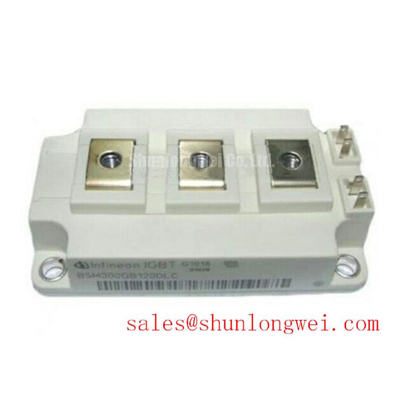
With the drive isolated and its DC link discharged, compare the installed module marking with the replacement request, then check the terminal layout before removing any busbar connections. The BSM35GB120DLC is an Infineon IGBT module rated at 1200 V and 35 A (Official Specification); its specified package category is Module (Official Specification). Those ratings establish an initial identification check, not approval for a particular inverter or spindle drive. Record the original connection positions, mounting arrangement and fault history so that the electrical and mechanical comparison remains tied to the actual equipment.
For a compact industrial inverter or high-speed CNC spindle drive under evaluation, first compare the original circuit diagram with the module connections. Confirm which switch positions the assembly serves, how gate commands reach them and where the drive senses a fault. The 1200 V rating is the module’s official voltage specification, but operating headroom also depends on DC-link conditions and switching overshoot. As a Design Consideration, capture the collector-to-emitter waveform during controlled testing rather than treating the DC-link reading alone as the peak voltage.
Short-circuit detection and shutdown belong to the surrounding gate-drive system. A fault can develop while a switch is being commanded on or while it is already conducting; the sensing method must be assessed for both conditions. Designers should verify detection delay, blanking behavior and the module’s applicable short-circuit safe operating information against the original manufacturer documentation. No short-circuit withstand time or shutdown threshold is specified in the supplied product parameters, so neither should be assumed for this unit.
A staged or otherwise controlled turn-off can be evaluated as a Design Consideration when abrupt fault shutdown produces excessive inductive overshoot. Probe the fault signal, gate voltage and collector-to-emitter voltage together under an approved test procedure. If the measured peak rises during shutdown, inspect the current-return path and gate-drive response before changing protection settings. Keep power-current paths compact and maintain clear separation between switching conductors and fault-sense wiring; final spacing must be checked against the equipment’s insulation design, not inferred from the module’s voltage rating.
Transient Dynamics and Electrical Design: Losses, Gate Resistance and Thermal Response
A 35 A official current rating does not describe the temperature reached during repetitive acceleration, braking or other pulsed loading. To assess an overload, obtain the manufacturer’s loss and transient thermal data for the exact device revision. An Engineering Calculation can then combine conduction and switching losses with the documented thermal impedance response to estimate peak junction temperature. Without those curves, a numerical junction-temperature margin would be unsupported.
Gate resistance affects switching speed and therefore both switching loss and voltage overshoot. Evaluate the installed gate network as a whole, including separate turn-on and turn-off paths if the equipment uses them. A faster edge may reduce one loss component while increasing stress elsewhere; the acceptable balance is system-determined. Similarly, minimize busbar loop inductance to limit turn-off overshoot, place any DC-link film capacitor or snubber in the intended low-inductance path, and verify the result with switching measurements. Do not assign a busbar inductance target from the module’s 1200 V rating.
During maintenance, inspect heatsink airflow, the condition of the thermal interface and the seating of accessible terminals. Compare measured case or heatsink temperatures under repeatable operating conditions with the equipment’s earlier service records where available. A changed temperature trend warrants checks of cooling and loading before it is attributed to the module. For broader context on gate-drive and thermal interactions, see IGBT Design & Integration.
When considering another module in the same purchasing review, BSM75GD120DLC can be examined as a separate part, not presumed interchangeable. Compare its official circuit configuration, terminal arrangement, dimensions, electrical limits and thermal requirements with the installed BSM35GB120DLC before making an equipment-level decision.
BSM35GB120DLC Thermal-Electrical Integration: Gate Isolation and Noise Checks
Isolation and common-mode transient immunity are properties to verify across the complete gate-drive arrangement. The supplied BSM35GB120DLC parameters do not establish a reinforced-isolation rating or a common-mode transient immunity rating. Designers should obtain the relevant module insulation data and gate-driver documentation, then check the actual barrier, supply arrangement and board layout against the equipment’s requirements. Infineon’s galvanically isolated gate-driver information provides context for evaluating driver functions; it does not assign a driver specification to this module.
On a drive with unexplained gate pulses or intermittent protection trips, compare the gate waveform at the driver output and at the module terminals during controlled switching. Check signal returns, connector seating and the routing of gate wiring near high-current conductors. Noise coupled into a fault-sense line can resemble a device fault, while a genuine switching disturbance may appear at both points. The measurements, rather than the symptom alone, should direct the next inspection.
Terminal creepage and clearance require an equipment-level review that includes the module connection area, busbars, contamination exposure and enclosure conditions. Moisture or condensation calls for an inspection of environmental controls and insulation surfaces; the voltage rating alone does not establish suitability for those conditions. Infineon’s power semiconductor information is useful background when separating component limits from driver and system responsibilities.
Maintenance note: Isolate and discharge the drive before reseating gate or power connections, and check the cooling path for obstructed airflow.
BSM35GB120DLC Operational Boundaries: Long Motor Leads and Reflected Voltage
Long motor cables introduce a separate question from the module’s collector-to-emitter rating. At fast switching edges, impedance differences along the cable and at the motor can produce reflected voltage at the motor terminals. That terminal waveform should not be assumed to equal either the DC-link voltage or the voltage measured across the IGBT. For a spindle-drive repair, record cable construction and length, motor insulation requirements and any existing output filter before deciding whether the replacement module is suitable for the original circuit.
If motor-terminal stress is suspected, measure the waveform with equipment and probe placement appropriate to the drive’s safety procedure, then compare it with measurements at the inverter output. A filter or choke may be evaluated as a Design Consideration when the measured waveform and motor limits justify it; selection depends on switching behavior, cable characteristics, motor requirements and the drive manufacturer’s guidance. Inspect filter connections and cable terminations as well, since an altered installation can change the observed waveform without changing the BSM35GB120DLC specification.