


Content last revised on October 3, 2026
CM100DU-12H Identification and Incoming Inspection
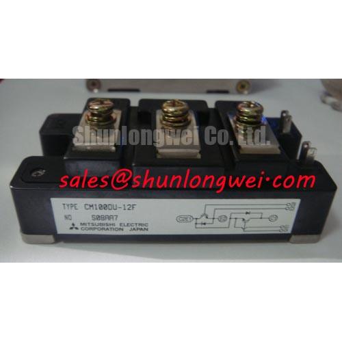
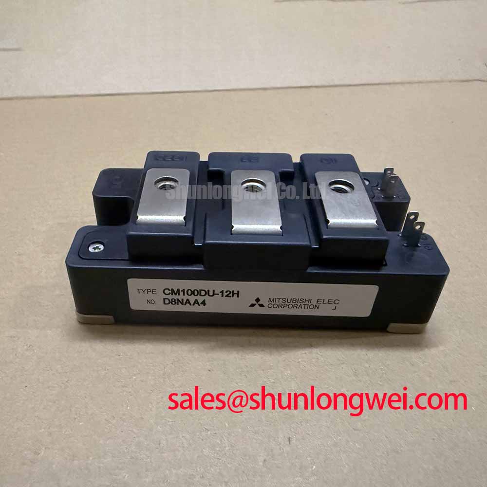
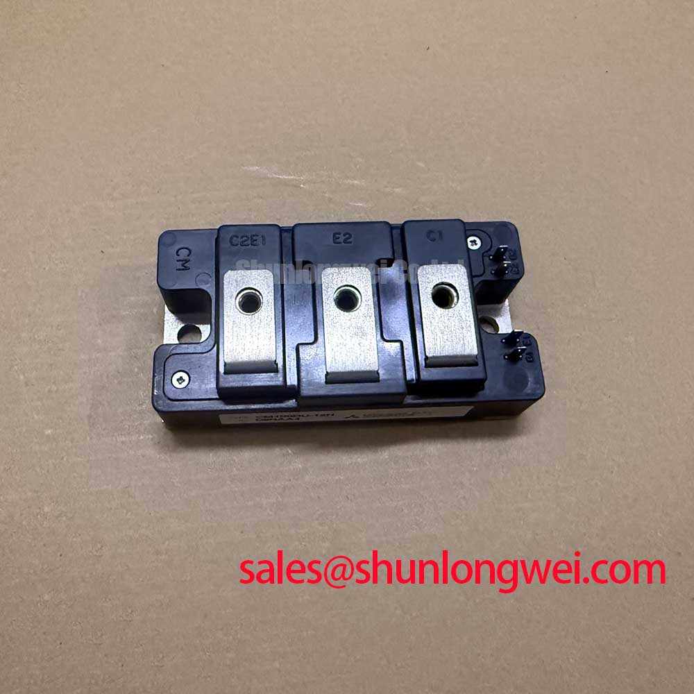
Start incoming inspection with the power terminals isolated and discharged, then compare the marking, terminal layout, and cold resistance pattern of the CM100DU-12H Mitsubishi Electric IGBT module against the approved maintenance record. The supplied official product data identifies this unit as a 600.0 V, 100.0 A, module type power semiconductor. Do not energize the assembly until the gate, collector, emitter, and auxiliary connections have been confirmed from the original equipment documentation.
| Parameter | Official Specification |
|---|---|
| Manufacturer | Mitsubishi Electric |
| Part number | CM100DU-12H |
| Rated voltage | 600.0 V |
| Rated current | 100.0 A |
| Package | Module |
These values are official product parameters supplied for this product page. They should not be treated as a complete switching, thermal, isolation, or surge specification. Before replacement, engineers should obtain the applicable Mitsubishi Electric documentation for gate limits, switching conditions, diode characteristics, insulation ratings, transient current capability, thermal impedance, and mechanical dimensions.
Preventing Spurious Faults: PCB Symmetry Considerations for Dual IGBT Guidelines for CM100DU-12H
When the equipment circuit confirms a dual IGBT arrangement, inspect the gate drive path as a current loop rather than as a simple signal trace. The auxiliary emitter return should follow the gate driver reference independently from the high current emitter path. Sharing a long section of copper between these two returns can introduce emitter voltage movement during rapid collector current transitions. That movement may appear at the driver reference and can produce an unwanted gate pulse or abnormal turn off behavior.
This is a Design Consideration, not a CM100DU-12H factory specification. Keep the power commutation loop compact, place the gate return beside its corresponding gate path, and preserve left to right symmetry between parallel current paths where the equipment topology requires matched devices. Avoid routing sensitive gate tracks beside the switching node for long distances. The final clearance and copper geometry must be established from the working voltage, pollution environment, insulation system, and applicable safety design requirements.
During field commissioning, first remove the control signal and verify that the gate to emitter resistance pattern is consistent with the approved service reference. A diode mode reading can help identify an unexpected conduction path, but a multimeter result alone cannot verify dynamic gate stability. With the module installed in a controlled test setup, compare gate to emitter waveforms at the driver output and directly at the module terminals. A difference between those locations may indicate trace inductance, common emitter coupling, probe grounding error, or a damaged interconnect.
Regenerative braking and resistor braking circuits deserve particular attention. During a forklift traction deceleration event, the chopper device may repeatedly transfer energy from the DC link into a braking resistor, where it is dissipated. Confirm that the resistor, contactor, DC link capacitor, and protection network are rated for the actual duty cycle. The CM100DU-12H voltage and current ratings do not, by themselves, establish the permissible braking pulse duration or energy absorption profile.
For maintenance teams evaluating potential replacement modules, the CM100DY-12E may be reviewed as a separate candidate. Engineers should compare the complete pin arrangement, electrical ratings, gate requirements, switching characteristics, mounting pattern, and thermal interface before approving any substitution.
Field Diagnostics & Commissioning: Common-Mode Transient Immunity in Harsh IGBT Topologies
Gate driver isolation is a system-level safety and functional requirement. The supplied product information does not establish a reinforced isolation rating above 5 kV or a common-mode transient immunity value above 100 kV per microsecond for this module. Those figures must be verified from the selected gate driver documentation, the insulation coordination file, and the equipment safety design. They should not be assigned to the CM100DU-12H solely because it is a 600 V module.
For a traction inverter or auxiliary converter, check the isolation barrier under the conditions specified by the driver manufacturer and the applicable equipment standard. Confirm the physical separation of primary and secondary circuits, the isolation components around the gate supply, and the return path used by measurement equipment. A probe ground lead connected at the wrong location can create an artificial common mode path and produce a misleading commissioning result.
A freewheeling diode can strongly influence the next switching event. Reverse recovery current may raise the commutation loop voltage and increase radiated or conducted interference. This behavior is topology dependent, so the diode data, DC link impedance, switching frequency, load current, and gate resistance must be assessed together. A snubber is an Engineering Recommendation only when waveform evidence shows that additional damping is appropriate. Its capacitor, resistor, layout, and pulse capability must be selected from measured overshoot and loss, not copied from an unrelated inverter.
Use a differential high voltage probe and a short, low inductance connection at the module terminals when checking collector to emitter overshoot. Compare the measured peak with the actual DC link voltage and the device documentation. If the waveform changes significantly when the probe position changes, inspect the measurement loop before changing the gate network. Oscillation may also come from the gate loop, the DC link laminate, a loose terminal, or an incorrectly routed auxiliary emitter return.
For broader application context, the Mitsubishi Electric power semiconductor reference material provides manufacturer background on high voltage IGBT technology. It should not be used as a substitute for the specific CM100DU-12H data required for production release. A converter topology reference such as this buck boost converter overview can assist with circuit interpretation, but it does not define the ratings of this module.
💡 Bench Tip: Use ESD protection and record a cold, unpowered terminal comparison before applying any gate or collector voltage, because a dynamic fault can be missed by an isolated diode mode check.
Transient Dynamics & Electrical Design: Thermal Paste Degradation Prevention on CM100DU-12H
Mounting quality directly affects the thermal path from the module base to the heatsink. Before installation, inspect both surfaces for foreign particles, burrs, scoring, and visible distortion. The thermal interface material should be applied as a controlled, continuous film suitable for the specified surface finish. The supplied product data does not specify a universal thermal paste thickness, so the material supplier’s application guidance and the module manufacturer’s mechanical instructions take priority.
This is a Design Consideration: excessive compound can increase thermal resistance, while incomplete coverage can leave air voids below the baseplate. Do not use paste to compensate for a visibly warped heatsink or a damaged mounting surface. Correct the mechanical condition first, then confirm contact coverage after the assembly procedure has been validated.
For a clamped assembly, verify that the pressure is distributed across the module base rather than concentrated at one corner. A flatness check, controlled fixture, and sequential tightening pattern are useful engineering practices. The actual screw type, torque, spring washer arrangement, and tightening order must come from the mechanical drawing or equipment service instruction. No CM100DU-12H mounting torque is provided in the official parameter set supplied here, so a generic torque value should not be presented as a product requirement.
Thermal cycling can gradually change interface contact through compound migration, fastener relaxation, heatsink movement, or repeated overload operation. During troubleshooting, compare the thermal response of each switching position under the same controlled load. An uneven temperature pattern may involve electrical current imbalance, sensor placement, poor clamping, blocked airflow, or a degraded interface. Use thermocouples or an approved infrared method with known emissivity limitations, and do not infer junction temperature directly from a case surface reading.
Regenerative braking can be especially demanding because the module may experience repeated power pulses rather than steady traction current. The braking resistor and control strategy should be checked for energy recovery behavior, pulse repetition, and cooling conditions. The official 600.0 V voltage and 100.0 A current values identify the device rating supplied for this page; they do not authorize operation at those limits under every temperature, switching frequency, pulse width, or cooling condition.
Assembly Integrity & Layout Architecture: Implementing Derating Guidelines and Mismatched Parameters for CM100DU-12H
When two switching paths operate in parallel, static current sharing may improve when the relevant forward voltage characteristic rises with temperature, but dynamic sharing remains strongly influenced by gate-loop impedance, driver timing, stray inductance, and layout symmetry. This behavior is a Design Consideration, not a guaranteed matching specification for the CM100DU-12H. Engineers should verify current balance with instrumented switching tests at the intended DC link voltage, load current, temperature, and braking profile.
Do not assume that equal copper length alone creates equal switching behavior. Match the complete gate path, including driver output resistance, connector transitions, auxiliary emitter return, and local decoupling. If one path shows earlier turn on, slower turn off, or a different voltage overshoot, inspect the physical loop and the driver channel before adding compensation components. Any gate damping change should be treated as a Typical Starting Point for bench tuning and confirmed by waveform, loss, and temperature measurements.
Long motor cables can behave as transmission structures at fast switching edges. Reflections may increase the motor terminal voltage beyond the voltage measured at the inverter, depending on cable length, impedance, termination, motor input capacitance, and switching transition speed. A cable filter, output reactor, or edge control network is a system design choice. Select and validate it from measured motor terminal waveforms rather than from the module rating alone. The test should cover acceleration, deceleration, regenerative braking, and abnormal load transitions.
Surge current testing also requires careful interpretation. The supplied official parameters do not include an ITSM value, a permitted surge duration, or a junction temperature recovery window. Those limits must be taken from the applicable Mitsubishi Electric technical documentation. During a suspected overload event, record the DC link waveform, gate command, collector current, heat sink temperature, and protection response together. A single peak current reading cannot establish whether the device remained within its safe operating area.
For equipment such as electric forklifts and warehouse material handling drives, replacement approval should include connector compatibility, busbar orientation, insulation distances, heatsink contact, control logic, braking duty, and the original system’s protection sequence. The Industrial Applications reference can support broader service planning, while the final acceptance decision should remain tied to the equipment schematic, the applicable module documentation, and measured commissioning results.
Before releasing the repaired assembly, inspect every power joint for controlled contact pressure, verify that the gate driver supply sequence follows the equipment design, and confirm that the module remains uncommanded during the isolation and precharge checks. The CM100DU-12H is documented here as a Mitsubishi Electric module rated at 600.0 V and 100.0 A; all additional operating limits must be confirmed against the correct technical documentation for the intended circuit.