


Content last revised on September 29, 2026
Preventing Spurious Faults: Gate Return Layout for the CM100DY-24NF
Probe the gate voltage at the module terminals during a switching test and compare it with the voltage measured at the driver output. A difference between those waveforms can expose voltage developed along the gate wiring or its return path. On a CM100DY-24NF installation, that distinction matters when an intermittent drive fault appears only under load: a clean waveform at the driver board does not establish that the gate sees the same signal.
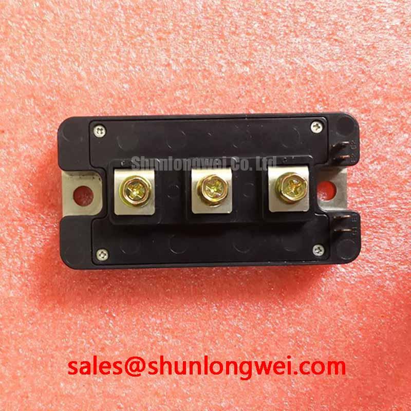
As a Design Consideration, keep the gate drive loop distinct from the high current power path wherever the module’s documented terminal arrangement permits. Current changes in a shared emitter conductor can move the driver’s apparent reference voltage and disturb switching. Do not assume that a separate Kelvin emitter connection exists on this module; identify the actual control and power terminals from its pinout before assigning a return conductor. Route the gate and its corresponding return together, avoid unnecessary loop area, and keep switching current paths away from sensitive control traces. Final conductor spacing and insulation clearance belong to the equipment design and must be checked against its operating voltage and applicable requirements.
If one switch position shows more ringing than another, compare gate trace length, connector condition, return routing, and the placement of any external gate resistor. Capture the gate waveform and collector voltage under the same operating conditions on a known working channel where one is available. This comparison is more useful than treating every oscillation as a defective module: wiring impedance, probe grounding, and driver behavior can produce similar symptoms.
For maintenance planning, record a baseline waveform after a verified repair and retain it alongside the drive’s circuit drawing. A later change in ringing or turnoff behavior then has a practical reference. In a heavy-duty variable frequency AC motor drive being assessed for this part, confirm that the original assembly’s terminal layout, drive arrangement, cooling interface, and electrical ratings match before treating the module as a compatible replacement.
CM100DY-24NF Operational Boundaries: Current Sharing and Switching Balance
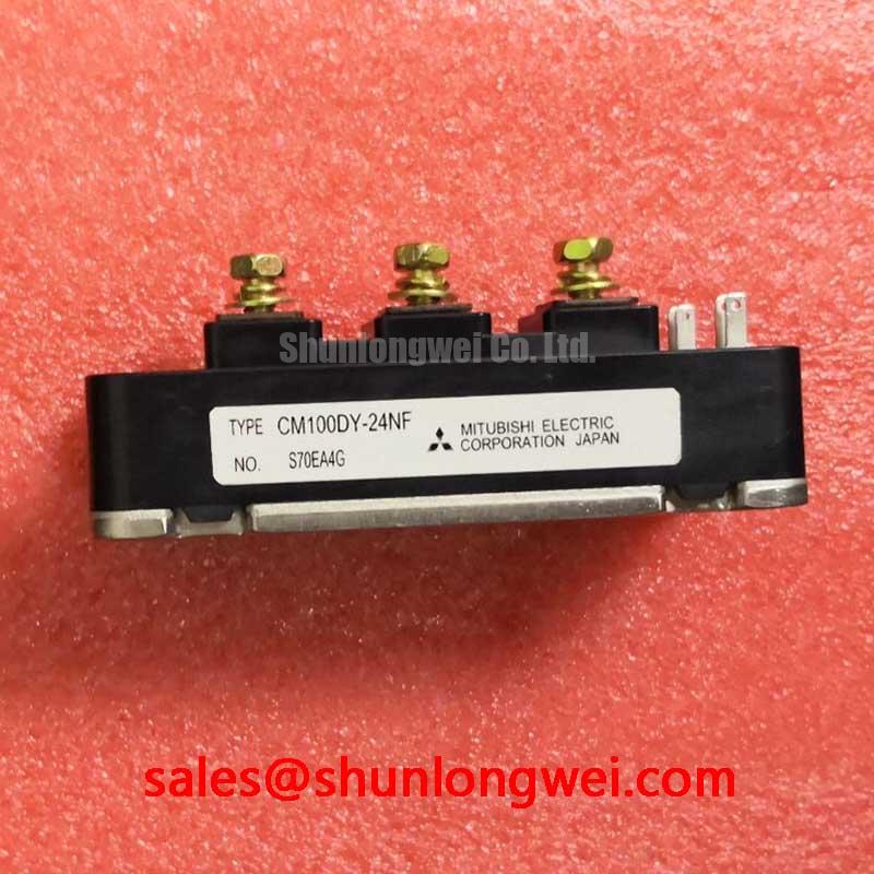
Measure the collector current and gate waveform in each relevant switching path when a repaired drive develops uneven heating or trips during acceleration. The 1200 V voltage rating and 100 A current rating are Official Specifications for CM100DY-24NF; neither rating, by itself, establishes acceptable current sharing in a particular converter. Bus voltage, load profile, switching events, and heat removal must be evaluated together.
Static and dynamic sharing are separate checks. As a Design Consideration, a positive temperature coefficient of on-state voltage can assist static current balancing under the conditions where that characteristic applies. It is not a substitute for measured device characteristics or matched thermal paths, and it should not be assumed as a verified characteristic at every operating point for this model. Dynamic balance depends heavily on gate path impedance, drive timing, and power loop geometry. Symmetrical wiring reduces avoidable differences, but the finished assembly’s waveforms decide whether the result is adequate.
When reviewing the driver, measure its ability to source and sink gate current during actual transitions rather than selecting it from the module’s current rating. Any external gate resistance is a Design Consideration to be tuned against observed overshoot, ringing, switching loss, and driver loading. Increasing damping can calm a waveform while also changing switching energy and temperature rise. The system engineer should establish the acceptable tradeoff through switching and thermal tests, without carrying an unverified resistor value into a repair instruction.
Check how the module interacts with the rest of the power stage. A rectifier or associated power device such as MPKB2SA100U60 belongs in a topology review of supply behavior and protection coordination, not in the gate driver circuit by assumption. Likewise, CM100DU-12H can be used as a catalogue comparison point, but its ratings, connections, mounting geometry, and switching characteristics need individual verification; similarity of model names does not establish interchangeability.
During a scheduled shutdown, inspect heatsink airflow, thermal interface condition, and the tightness of accessible electrical connections using the equipment’s approved service procedure. Rising case or heatsink temperature may reflect a cooling problem, a changed load, or altered switching behavior. Record operating conditions with each temperature reading so that maintenance trends are comparable.
Transient Dynamics: Voltage Headroom, Recovery, and Environmental Risk
Capture collector voltage at turnoff while the drive operates through its most demanding verified load transition, then compare the peak with the 1200 V Official Specification. The DC bus reading alone can miss an inductive overshoot at the module. As a Design Consideration, minimize parasitic power loop inductance to limit that overshoot, then verify the remaining voltage margin on the assembled converter with suitable high voltage measurement practices.
Commutation also deserves attention. If the circuit uses a freewheeling diode, its reverse recovery behavior can influence current spikes, voltage ringing, and conducted or radiated interference. Recovery softness is a useful engineering concept, but no recovery softness factor is stated in the supplied specifications for CM100DY-24NF. Identify the documented diode arrangement and characteristics before assigning a numerical factor to this module. Compare measured commutation waveforms rather than inferring diode behavior from the IGBT current rating.
A current pulse can raise junction temperature faster than a heatsink sensor responds. Transient thermal impedance, when available in the applicable manufacturer documentation, helps relate pulse duration and power dissipation to that temperature rise. Without a verified thermal impedance curve and the installation’s measured losses, a numerical peak junction temperature would be speculative. Check the thermal interface for deterioration, clear obstructed cooling passages, and compare temperatures under repeatable loads before attributing a heat related trip to the semiconductor alone.
Altitude related neutron exposure and single event burnout are system reliability considerations, not grounds for a calculated failures in time figure from the voltage rating. No model specific FIT data, neutron test result, or altitude derating rule is provided here. For an installation where those risks matter, the Design Consideration is to review documented device reliability information and the operating DC bus voltage with the equipment’s reliability team; do not convert an assumed altitude or voltage margin into a promised lifetime. Wide Bandgap Revolution provides broader context for comparing power device design challenges, not a reliability qualification for this IGBT module.
Mitsubishi Electric’s NX-Series IGBT Modules material and SiC power device information describe other manufacturer product families and technology considerations. They should not be read as specifications, test evidence, or certification for CM100DY-24NF.
Assembly Integrity: Checking Gate Coupling and Turnoff Protection
Measure the off state gate voltage while the neighboring switch commutates and investigate any repeatable voltage rise before returning the drive to service. Capacitive coupling from collector to gate can inject current during a rapid voltage transition; whether that disturbance produces an unintended turnon depends on the installed driver, wiring, and device characteristics. Compare the observation with the driver’s fault record and the collector waveform rather than assigning a single cause from one trace.
An active Miller clamp is a Design Consideration when off state gate disturbance remains unacceptable. Confirm that the selected driver provides the intended clamp function, that its connection reaches the correct gate reference, and that its operating sequence is compatible with the equipment’s protection scheme. A negative off state gate bias is another possible circuit level measure, but its value cannot be prescribed from the module’s voltage and current ratings. Gate voltage limits, driver capability, and measured transient behavior must govern that decision.
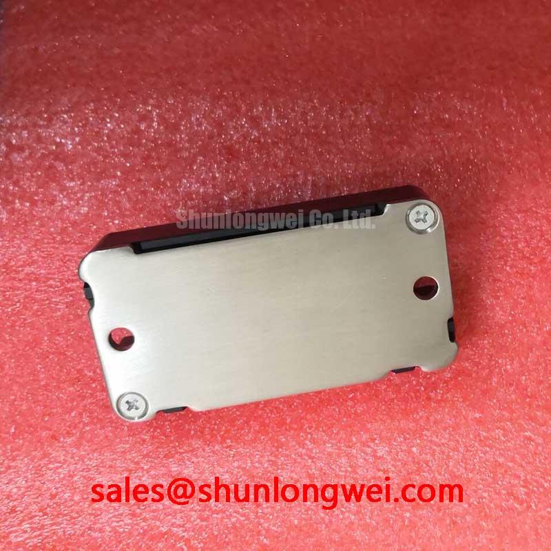
Inspect the mechanical installation at the same time. Uneven contact with the heatsink, aged thermal material, blocked airflow, or a loose power connection can change operating temperature and obscure an electrical diagnosis. Use the equipment manufacturer’s approved fastening and thermal interface instructions rather than assuming a torque or coating thickness for an unspecified fastener. Where cold starts or humid shutdowns are routine, inspect for condensation and contamination before energizing the assembly.
Maintenance Note: Isolate and discharge the DC bus before touching module terminals, then monitor connection temperature and heatsink airflow after the repair.
For the final functional check, log gate and collector waveforms together with load current and cooling conditions. If turnoff ringing, off state gate rise, or temperature differs from the established baseline, revisit the driver return path, protection timing, and mounting contact in that order of measurement, adjusting only what the observed fault and the equipment documentation support.