

Content last revised on September 10, 2026
Assembly Integrity & Layout Architecture: Implementing Galvanic Gate Drive Isolation for CM100TJA-24FA
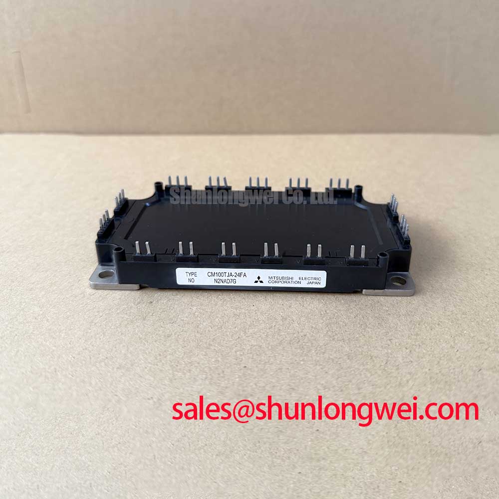
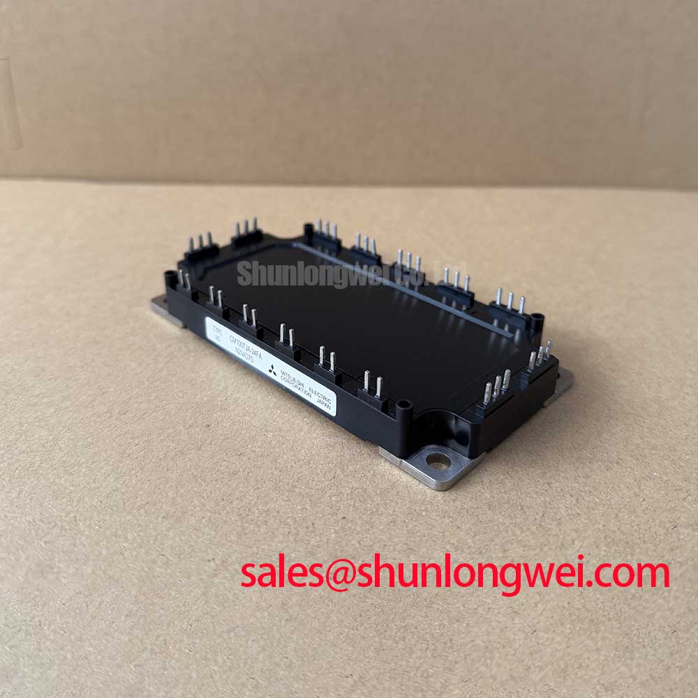
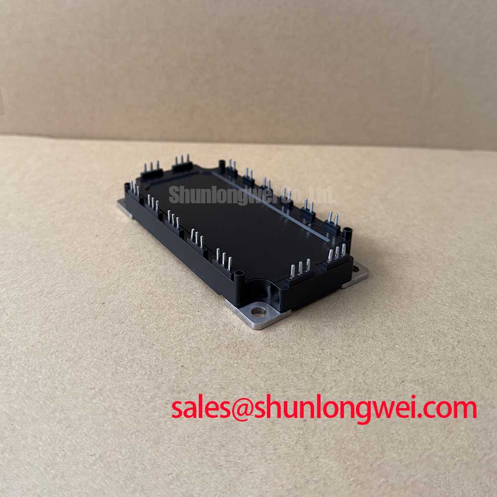
With the drive system isolated and the DC link safely discharged, inspect the CM100TJA-24FA terminal area for heat discoloration, loose hardware, contaminated mounting surfaces, and abnormal cold-state resistance paths before reconnecting any gate-drive or power wiring. The CM100TJA-24FA from Mitsubishi Electric is an IGBT power module rated at 1200 V and 100 A according to the Official Datasheet Specification supplied for this product. Its listed package style is Module; the installer should verify the original equipment documentation for the exact circuit topology, terminal assignment, driver connection, and mounting geometry before installation.
| Parameter | Specification |
|---|---|
| Product model | CM100TJA-24FA |
| Manufacturer | Mitsubishi Electric |
| Rated voltage | 1200 V Official Datasheet Specification |
| Rated current | 100 A Official Datasheet Specification |
| Package | Module |
Start an installation review by tracing the gate-driver return path back to the power-emitter reference used by the original equipment. A gate signal can look correct at the controller connector yet arrive distorted at the module when the return conductor shares a noisy power path. This is especially relevant during repair of motor drives, chargers, and forklift traction inverters, where switching-current loops and control wiring are often routed within the same compact enclosure.
Galvanic isolation is a system-level function provided by the gate driver and its associated insulation barrier, not an Official Datasheet Specification stated for the CM100TJA-24FA module itself. Design Consideration: the selected driver insulation rating and common-mode transient immunity should be reviewed against the actual DC-link conditions, layout clearances, cable routing, and measured switching waveform behavior. Requirements sometimes described as reinforced isolation or high common-mode transient immunity must be assigned from the equipment safety architecture and verified through the driver documentation and system test plan.
Keep the gate-drive conductors paired with their intended return paths and avoid long, separated gate wiring. This helps limit loop inductance that can turn a fast collector-emitter voltage transition into a false gate disturbance. Where unexplained switching occurs, inspect the gate-driver supply stability, probe gate-emitter voltage directly at the module connection using appropriate measurement practice, and compare the waveform with a known-good phase or channel. A distorted waveform may indicate return-path coupling, probe-induced measurement error, driver malfunction, or layout imbalance; it should not be attributed to one cause without evidence.
Terminal creepage and clearance must follow the requirements of the end equipment, its operating environment, and the applicable electrical safety design rules. Moisture, conductive dust, and residue around module terminals can undermine a layout that appears adequate when clean. For practical reference on power-device operating principles and safe measurement context, maintenance teams can consult The Ultimate IGBT Knowledge Base.
Benchtop Waveform Tuning: Mitigating Stress via Multi-Module Parallel Current Sharing on CM100TJA-24FA
Before considering parallel operation, establish whether the original inverter was designed for a single CM100TJA-24FA location or for multiple modules operating together. The product information supplied identifies voltage, current, and package category, but does not define a parallel connection scheme. Engineers should therefore verify the original schematic, module matching requirements, gate-driver arrangement, and protection architecture before any change is made.
Design Consideration: IGBT conduction behavior often includes a positive temperature coefficient over relevant operating regions, which can support steady-state current sharing when devices are appropriately matched and thermally managed. It does not, by itself, guarantee balanced dynamic current sharing. During turn-on and turn-off, unequal gate resistance, unequal trace length, different busbar geometry, and unequal thermal conditions can cause one position to carry more transient stress than another.
A useful bench procedure is to capture collector-emitter voltage and current waveforms from each parallel path under controlled operating conditions. Compare timing, current rise, current decay, and ringing characteristics rather than relying on static resistance checks alone. If one path switches earlier or has visibly different overshoot, inspect its gate loop and power loop geometry before changing component values. Any gate damping adjustment should be treated as a Typical Starting Point for controlled bench tuning, with final settings determined from measured voltage margin, temperature behavior, and protection response in the completed equipment.
Thermal interface quality also affects current balance. A thin, continuous thermal interface material layer is a Design Consideration evaluated according to the heatsink flatness, material datasheet, and assembly method; it is not an Official Datasheet Specification for this module. Use the mounting torque, tightening sequence, and hardware specification stated by the original equipment or module mechanical documentation. A cross-pattern tightening sequence can help distribute clamping force across the module baseplate when the hardware arrangement permits it.
⚠️ Maintenance Note: Periodically monitor terminal and heatsink contact temperature rise, clear the cooling airflow path, and recheck mounting hardware only according to the equipment manufacturer’s maintenance procedure.
When an existing repair bill of materials identifies a related Mitsubishi Electric module for evaluation, the CM100DY-12E can be reviewed against the original schematic, electrical ratings, package outline, terminal layout, and gate-drive requirements. It should not be assumed to be a direct replacement without that equipment-specific verification.
CM100TJA-24FA Circuit Protection & Reliability: Calibrating SCSOA Overcurrent Protection
Overcurrent protection must be assessed at the inverter level because the supplied CM100TJA-24FA product information does not state short-circuit withstand time, short-circuit safe operating area limits, desaturation threshold, or soft-turn-off profile. These values must come from the applicable official device documentation and the original drive design. It is unsafe to assign a short-circuit response target such as less than ten microseconds to this module without a verified SCSOA specification and a measured protection-chain response.
In service work, inspect the entire protection chain rather than focusing only on the power module. This includes the current-sensing path, gate-driver desaturation circuit where used, fault logic, isolated power supplies, controller fault input, gate-discharge route, and the DC-link bus structure. A power stage that repeatedly reports overcurrent may be responding to a genuine load fault, a measurement reference problem, unwanted gate drive, insufficient gate-drive supply integrity, or switching noise entering the protection signal.
Type I and Type II short-circuit terminology may be used in power-electronics design discussions, but the classification and allowable response depend on the application topology and official semiconductor data. Engineering Recommendation: use an oscilloscope and suitable isolated measurement method to confirm the sequence from fault detection through gate command removal, collector-emitter voltage behavior, and DC-link response. The purpose is to establish whether the system is turning the device off under controlled conditions rather than allowing inductive energy to create excessive voltage stress.
Soft turn-off is commonly implemented by a gate driver to reduce the rate of current interruption after a fault has been detected. It is a driver and system protection function, not a declared feature of the CM100TJA-24FA based on the supplied specifications. Its effectiveness depends on the DC-link inductance, motor or load current, busbar arrangement, driver output path, and actual switching conditions. Minimize parasitic inductance in the commutation loop to suppress turn-off overshoot, then verify peak voltage behavior against the DC-link voltage and the module’s 1200 V official rating during controlled switching tests.
Mitsubishi Electric’s Power Semiconductors & High-Power Modules resource provides useful manufacturer-level context for power-device technology. Device-level electrical limits, protection settings, and waveform acceptance criteria should still be taken from the documentation applicable to the exact module and equipment revision.
CM100TJA-24FA Thermal-Electrical Optimization: Transient Thermal Impedance Practical Tuning
Thermal inspection begins at the physical interface: remove accumulated dust from heatsink fins and fan guards, inspect airflow direction, check for blocked intake filters, and look for dried, displaced, or contaminated thermal interface material during scheduled service. On an electric material handling or forklift low-voltage traction system, repeated acceleration and regenerative events can produce pulsed loading that is not represented by a single steady-state current reading.
The CM100TJA-24FA is officially rated at 100 A, but that rating alone does not establish allowable junction temperature under a particular pulse train, heatsink condition, switching frequency, ambient temperature, or cooling arrangement. The thermal impedance curve, junction-to-case thermal data, maximum junction temperature, and module mounting requirements must be verified from the applicable official documentation before calculating a junction-temperature margin.
Engineering Calculation can use a multi-RC thermal model when verified transient thermal impedance data are available. In practical terms, each recent power pulse contributes a time-dependent temperature rise, and the device may not fully cool before the next pulse arrives. The resulting peak junction temperature is assessed by combining calculated device loss with the appropriate transient thermal response and the measured or estimated case temperature. No numerical thermal result should be assigned to this module without its official thermal curves and the actual duty cycle.
During preventive maintenance, compare operating case temperatures between similar inverter positions under equivalent load where safe access and measurement methods permit. A persistent difference may indicate heatsink contamination, airflow imbalance, poor interface contact, unequal switching loss, or a loading difference upstream in the machine. Check fasteners, cooling fans, thermal pads or grease condition, and terminal tightness before assuming a semiconductor fault.
High-altitude operation, cosmic-ray exposure, single-event burnout behavior, lifetime prediction, insulation reliability, EMC compliance, and failure-rate figures require source-specific qualification data. No such figures are stated in the supplied CM100TJA-24FA parameters. System designers should evaluate these risks through the equipment’s applicable standards, environmental profile, manufacturer documentation, and controlled validation. Additional semiconductor technology information is available from Mitsubishi Electric Global Semiconductor Device Technologies.