Content last revised on October 3, 2026
CM1200DC-34S Voltage Margin and Environmental Evaluation
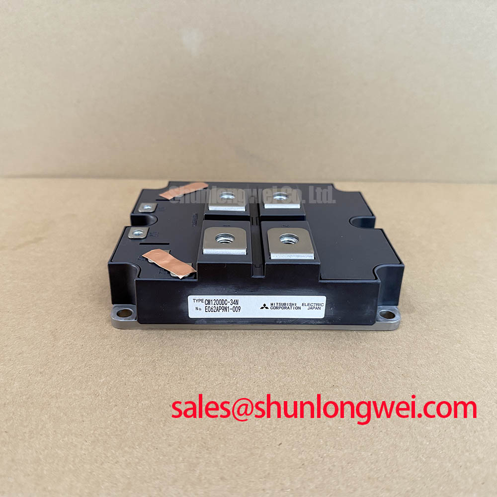
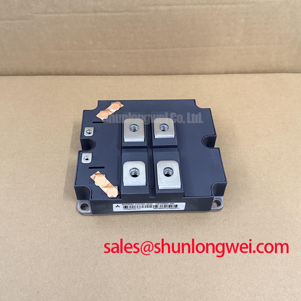
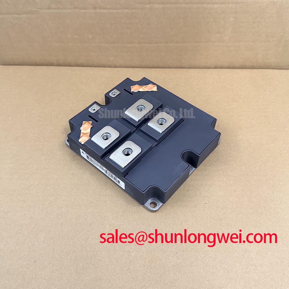
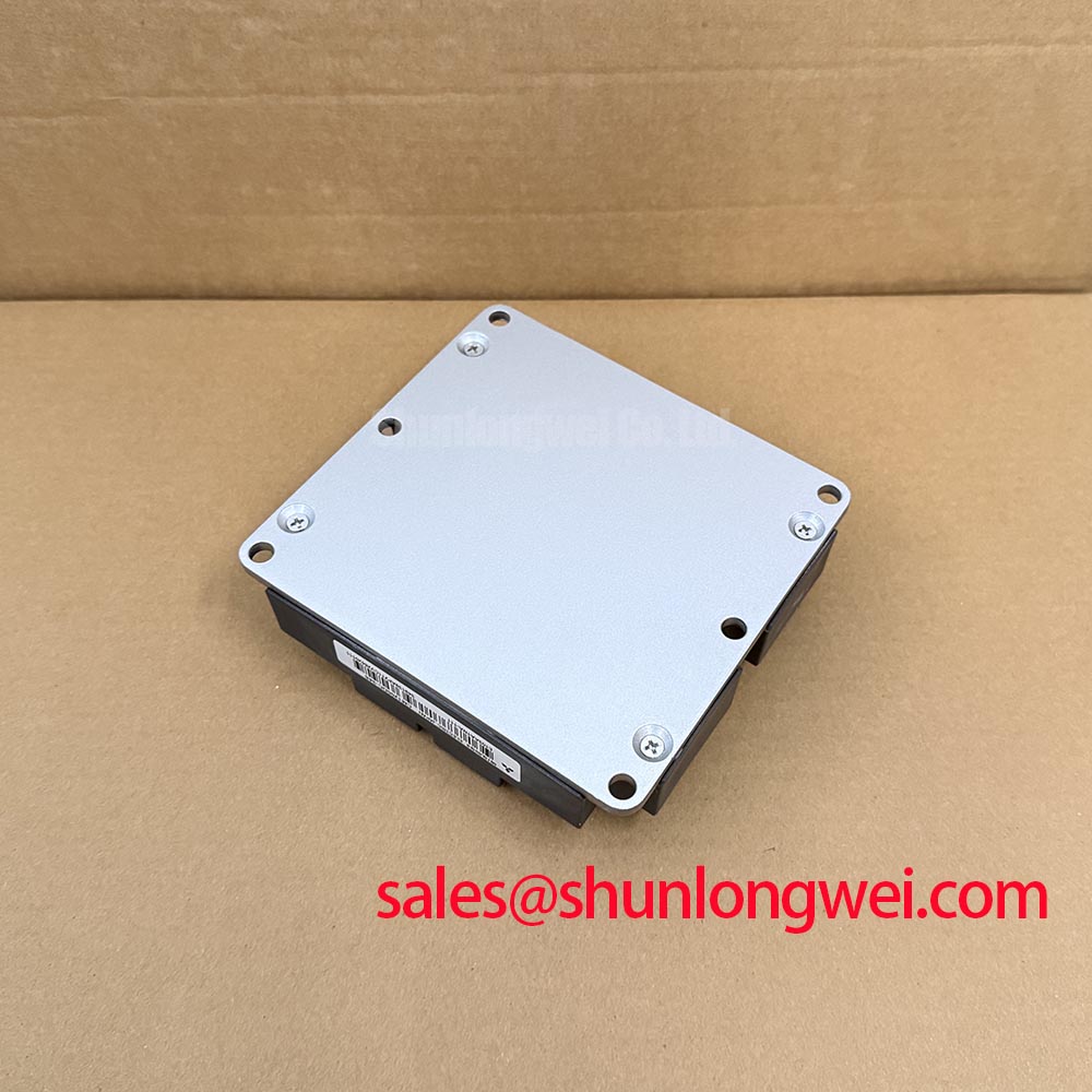
Verify the module nameplate and the disconnected assembly’s terminal layout before evaluating CM1200DC-34S for a repair. The confirmed product identity is a Mitsubishi Electric IGBT module with a 1700 V voltage rating and a 1200 A current rating, both Official Specifications supplied for this product page. Those ratings establish an initial comparison point; they do not establish the assembly’s bus voltage, allowable overload, mounting arrangement or gate-drive settings.
Record the equipment’s normal DC-link voltage and capture its highest switching transient under representative operating conditions. Compare both with the module’s 1700 V rating (Official Specification), rather than treating the steady bus reading as the complete voltage-stress picture. As a Design Consideration, wiring inductance, switching speed and fault interruption can affect the voltage seen at the module terminals. The system engineer should establish the required operating margin from measured waveforms and the applicable Mitsubishi Electric documentation.
For a wind turbine full-scale converter, compatibility remains an assembly-level question. A matching voltage rating does not confirm that the original busbar, cooling hardware, gate drive and protection sequence suit this module. Trace the installed power circuit before assigning it a topology. A forward converter and a matrix converter illustrate different switching arrangements; neither description identifies the topology of equipment containing CM1200DC-34S.
Cosmic-ray-related device failure and altitude-related derating cannot be reduced to a defensible failure-in-time figure from the voltage rating alone. As a Design Consideration, an installation at altitude warrants review of the manufacturer’s applicable environmental guidance and the complete converter’s insulation coordination. Do not infer a clearance dimension or a terrestrial-neutron failure rate for this model without the relevant device and system data. During fault investigation, retain the recorded bus-voltage history and switching captures so an intermittent trip can be checked against observed electrical stress rather than attributed to a single assumed cause.
CM1200DC-34S Gate-Drive and Thermal-Electrical Integration
Start with the existing driver schematic and the original module documentation. Identify the gate-command path, turn-off path, protection feedback and any clamp circuit before changing components. Rapid voltage transitions can couple into a gate circuit; if an apparent unwanted turn-on is suspected, compare gate-to-emitter waveforms at the module connections with the driver command while observing the required measurement safety procedures. This is a Design Consideration for diagnosing the converter, not a specified susceptibility threshold for CM1200DC-34S.
An active Miller clamp or negative gate bias is a system-design option, not a setting established by the 1700 V, 1200 A product ratings. The designer should check the original driver requirements, permitted gate limits and measured turn-off behavior before selecting either approach. Keep the gate return path controlled and inspect connector seating and wiring condition; an unexplained change in waveform shape may originate in the driver path as well as in the power stage.
At the cooling interface, inspect the heatsink for blocked airflow and check the thermal interface material during scheduled maintenance. The appropriate replacement material, application method and mounting procedure must come from the assembly and module documentation. A rising case or heatsink temperature deserves comparison with load, ambient conditions and airflow records before it is assigned to the semiconductor alone. Maintenance note: Isolate the converter and confirm its DC link is discharged before disturbing module connections.
Benchtop Waveform Checks for Parallel CM1200DC-34S Modules
If the converter uses parallel modules, first confirm that the installed circuit actually places their corresponding power paths in parallel. The 1200 A rating (Official Specification) is a module rating; it does not, by itself, authorize multiplying ratings to establish an assembly current limit. Busbar geometry, cooling differences and gate-drive timing can all affect how current divides during switching.
As a Design Consideration, compare the physical lengths and routing of corresponding power and gate paths, then capture switching waveforms under controlled test conditions. Look for differences in turn-on and turn-off timing, voltage overshoot and current distribution. Equal-looking static connections do not guarantee dynamic sharing. Likewise, do not assume a particular positive temperature coefficient of on-state voltage for this model without its characteristic curves and operating conditions; use the applicable datasheet data and measured temperatures when assessing steady-state balance.
A replacement assessment should also compare circuit position, terminal arrangement, driver compatibility and thermal mounting, not just headline ratings. The FF45017ME4 is a separate model that can be examined in a cross-model comparison, but its suitability as a substitute cannot be concluded from its name or a shared voltage class. For the broader relationship between module selection, switching stress and system reliability, see the Power Electronics Masterclass; the installed converter’s documentation remains the authority for its acceptance criteria.
CM1200DC-34S Operational Boundaries Under Pulsed Load
When investigating an overload event, collect the current trace, pulse duration, repetition pattern and available temperature measurements. The module’s 1200 A current rating (Official Specification) cannot establish permissible pulsed operation without its stated test conditions and thermal data. A transient junction-temperature estimate would require an applicable loss calculation and junction-to-case transient thermal-impedance information; neither can be reconstructed reliably from the two headline ratings.
Compare the event record with the original protection sequence and inspect the cooling path before returning the assembly to service. Clean obstructed heatsink passages, verify fan or coolant operation where applicable, and check terminal fastening against the equipment’s documented procedure. If temperature readings differ between comparable module positions, examine sensor placement, load sharing and thermal contact before drawing a conclusion about an individual device. The system engineer should determine acceptable peak-temperature margins using the manufacturer’s detailed characteristics and measured converter duty cycle.