

Content last revised on November 1, 2026
Preventing Spurious Faults: Desaturation Detection Guidelines for CM150RL-24NF
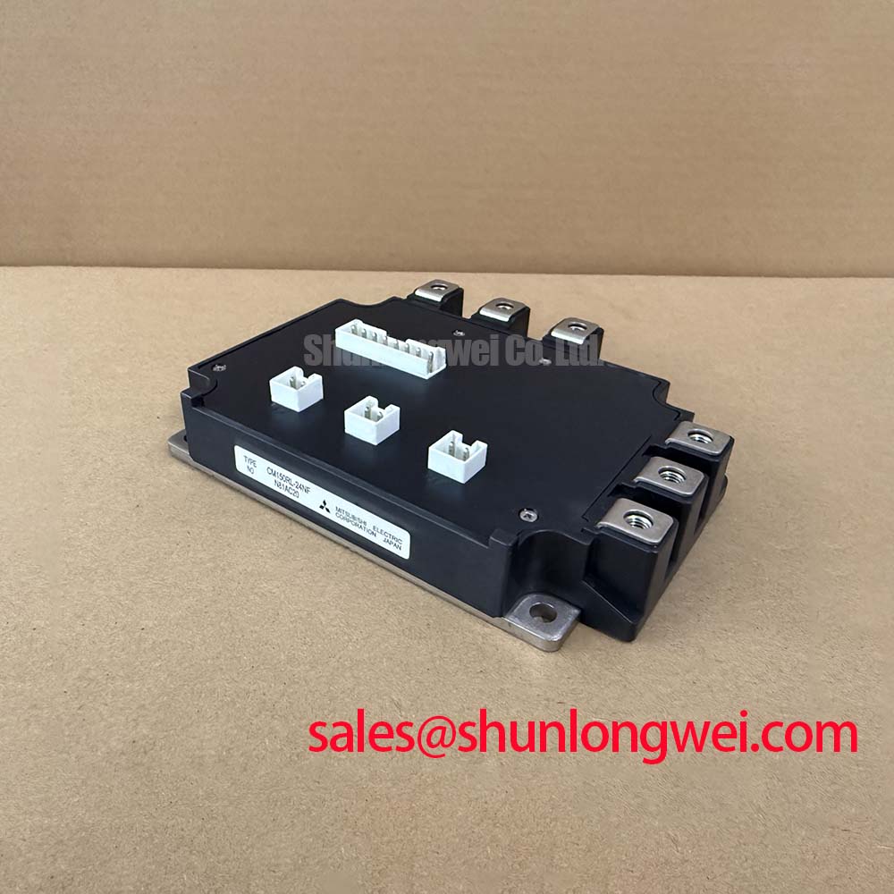
I check the relationship between the gate command, collector-emitter voltage and protection output before treating a desaturation trip as evidence of module failure. For the Mitsubishi Electric CM150RL-24NF, this means examining the external gate driver and its sensing connections alongside the power stage. The integrated NTC provides temperature feedback; it does not establish that the module contains autonomous desaturation detection, short-circuit interruption or thermal shutdown.
Design Consideration: distinguish a fault present when the IGBT turns on from a fault developing while it is already conducting. These conditions are commonly described as type-I and type-II short circuits, respectively, and can produce different current and voltage trajectories. The protection chain includes sensing, blanking, filtering, driver propagation and the actual current interruption. Its complete response must fit the applicable manufacturer short-circuit withstand conditions, rather than an assumed universal microsecond limit.
A nuisance trip deserves a timing investigation before a threshold adjustment. Compare the desaturation signal with the collector voltage transition and the driver reference using appropriately rated, isolated measurement equipment. Noise coincident with a switching edge can originate in sensing-loop coupling, reference movement or probe pickup. A voltage that remains elevated while the gate is commanded on calls for a different investigation, including gate-drive delivery, load condition and connection integrity. Neither observation alone identifies a failed module.
Engineering Recommendation: keep the desaturation sensing route separated from high-current commutation paths and preserve the driver manufacturer’s required clearances. Avoid routing the sensing return through a power-current connection that can introduce transient reference error. Clearance and creepage dimensions belong to the complete insulation design and its operating environment, not to a generic spacing rule attached to this part number.
Where the driver supports staged soft shutdown, evaluate how its initial gate discharge and subsequent turn-off affect both fault energy and collector-voltage overshoot. Slowing current interruption can reduce inductive overvoltage, but it also changes the energy dissipated during the fault. Protection validation should therefore assess the complete waveform within the applicable safe operating boundaries. Simply extending blanking to suppress an intermittent alarm can hide the event the circuit was intended to detect.
CM150RL-24NF Thermal-Electrical Optimization: DC-DC Converter Interleaving and Ripple
Compare the NTC trend with load direction, heatsink temperature and cooling condition before attributing repeated thermal alarms to inadequate semiconductor capacity. The 150 A collector-current rating and −40 to +150°C junction-temperature range are official specifications, not a continuous operating prescription for an assembled converter. The allowable operating point depends on the electrical test conditions, semiconductor losses and complete thermal path.
Design Consideration: engineers evaluating this module for a commercial string inverter or micro-grid energy-storage converter should map its 7-pack inverter and brake chopper configuration against the actual schematic. Bidirectional battery-to-link power transfer, interleaved DC-DC conversion and four-quadrant inverter operation are system functions; the module configuration alone does not establish those capabilities. Verify the required switching positions, current paths and brake function before treating the package as a topology match.
Where the surrounding converter uses interleaved branches, inspect branch-current balance and phase timing under the intended operating conditions. Interleaving can redistribute ripple, but unequal branch impedances or control timing can concentrate heating. Compare charging and discharging operation separately, because their conduction and commutation paths need not produce identical losses. Peak-shaving duty also deserves examination across repeated load transitions rather than only at a settled operating point.
At the mechanical interface, inspect heatsink flatness, mounting surfaces and the condition of the thermal interface material during planned service. Engineering Recommendation: use the specified interface material and assembly procedure to achieve coverage without unnecessary thermal resistance. A universal paste thickness is inappropriate without the material characteristics and mounting instructions. If the approved assembly process specifies progressive cross-pattern tightening, follow its sequence and specified torque using a calibrated tool.
Maintenance Note: Trend terminal temperature rise and inspect cooling airflow during scheduled service, with any terminal tightening performed only after isolation and verified discharge under the equipment maintenance procedure.
Set inspection intervals from contamination, load history and the equipment maintenance requirements rather than an invented module replacement schedule. Dust accumulation, impaired fan performance and disturbed thermal interfaces can each change the temperature trend. After service, compare measurements at equivalent load and ambient conditions. In environments subject to temperature transitions, assess condensation control before energization; a junction-temperature rating is not a moisture-resistance specification.
The NTC is useful for tracking the thermal condition at its sensing location, but it should not be treated as a direct measurement of the hottest semiconductor junction. Interpret its signal through the equipment’s validated thermal model and protection strategy. A changing relationship between NTC indication and heatsink temperature can justify inspection without establishing a single cause.
Benchtop Waveform Tuning: Mitigating Stress via Symmetrical Busbar Geometry on CM150RL-24NF
Inspect the outgoing and return commutation paths together when collector-voltage overshoot changes after a module replacement or busbar repair. Design Consideration: closely coupled current paths and controlled connection geometry can reduce parasitic inductance, while long connections and expanded loop area can increase switching stress. The practical acceptance criterion is the measured voltage waveform under representative operating conditions, not a visually symmetrical assembly alone.
The 1200 V collector-emitter rating establishes an electrical boundary for the CM150RL-24NF. During switching evaluation, consider the DC-link level together with transient excursions at the device terminals. Use probes with suitable ratings and measurement performance, and document their connection locations. Different probing loops can change the apparent ringing sufficiently to mislead a comparison between an original assembly and a repaired one.
For assemblies that parallel switching devices, equalize relevant power-path impedance and gate-drive routing before assessing current sharing. Match driver-reference arrangements as carefully as gate conductors, because a shared return impedance can alter the effective gate-emitter voltage. Static sharing and dynamic sharing are separate questions: comparable settled currents do not demonstrate balanced current during switching transitions.
The official 2.1 V typical VCE(sat) at 25°C is a conduction characteristic, not proof of a universally positive temperature coefficient. Engineering Recommendation: examine the manufacturer’s output characteristics over the intended current and temperature range before relying on temperature-dependent voltage drop to assist current sharing. A typical value at a single temperature cannot establish parallel-operation suitability or predict the hottest branch.
Replacement assessment should also separate electrical family resemblance from actual interchangeability. If a maintenance shortlist includes the CM50MX-24A, compare its own ratings, circuit configuration, terminal map, mounting dimensions and driver requirements with the equipment documentation. It should not be designated a compatible substitute merely because it shares the Mitsubishi module naming convention. Record the comparison before any substitution decision.
Thermal cycling also warrants restrained interpretation. The general subject of wire bonding and metallurgical reliability in power semiconductor modules provides background on electrical interconnection methods, but does not establish this model’s internal construction or service life. Maintenance decisions should rely on repeatable measurements, assembly condition and applicable manufacturer guidance rather than inferred internal materials or unsupported lifetime estimates.
CM150RL-24NF Thermal-Electrical Optimization: Diode Recovery and Practical Tuning
Capture the commutating current alongside collector-emitter voltage when investigating ringing near IGBT turn-on. Design Consideration: reverse recovery of a conducting freewheeling diode can contribute to the incoming switch’s current peak and excite the commutation loop. Its observed behavior depends on current, temperature, switching rate and circuit inductance. A ringing trace alone does not establish that the diode is damaged or that its recovery is intrinsically unsuitable.
Evaluate peak reverse-recovery current and the shape of the recovery tail under comparable test conditions. A more abrupt current collapse can excite a different transient response from a gradual recovery, even where individual peak readings appear similar. Diode softness is a measured characteristic under defined conditions, not an externally adjustable module setting. Changes to the surrounding circuit alter commutation behavior; they do not rewrite the diode’s intrinsic characteristics.
Engineering Recommendation: assess turn-on gate resistance as part of the complete driver and loss evaluation. Reducing switching speed can moderate the rate of current transfer and associated ringing, but may increase switching energy and temperature. Select the final arrangement from measured switching behavior and thermal performance across the intended operating range, rather than applying an undocumented resistance value to this module.
An RC snubber likewise requires circuit-specific evaluation. Its effectiveness depends on where it connects, the parasitic network it addresses and the energy it must dissipate. Locate the relevant oscillation path before selecting components, then check component stress and heating during representative operation. A snubber attached through an extended connection may not control the local transient that prompted its installation.
For background on why switching stresses differ between circuit arrangements, Resonant Topologies in Home Appliances offers a topology comparison rather than a CM150RL-24NF qualification reference. Resonant and hard-switched stages impose different commutation conditions, so component values or waveform expectations should not be transferred between them without evaluating the actual circuit.
After a gate-drive or snubber change, repeat the waveform comparison at relevant load and temperature conditions and examine its effect on conducted and radiated noise at equipment level. The module’s electrical ratings do not confer system EMC compliance. Retain the probe arrangement, operating conditions and resulting traces in the service record so the next maintenance inspection can distinguish a circuit change from a measurement change.