

Content last revised on October 2, 2026
Assembly Integrity & Layout Architecture: High Altitude SEB Risk Review for CM150TF-12H
Begin incoming inspection by confirming the printed part designation, checking the power-terminal insulation surfaces for handling damage, and comparing cold-state terminal readings with a known-good circuit path before installing CM150TF-12H.
| Manufacturer | Mitsubishi Electric |
| Product type | IGBT Module |
| Rated voltage | 600V Official Specification |
| Rated current | 150A Official Specification |
| Package | Module Official Specification |
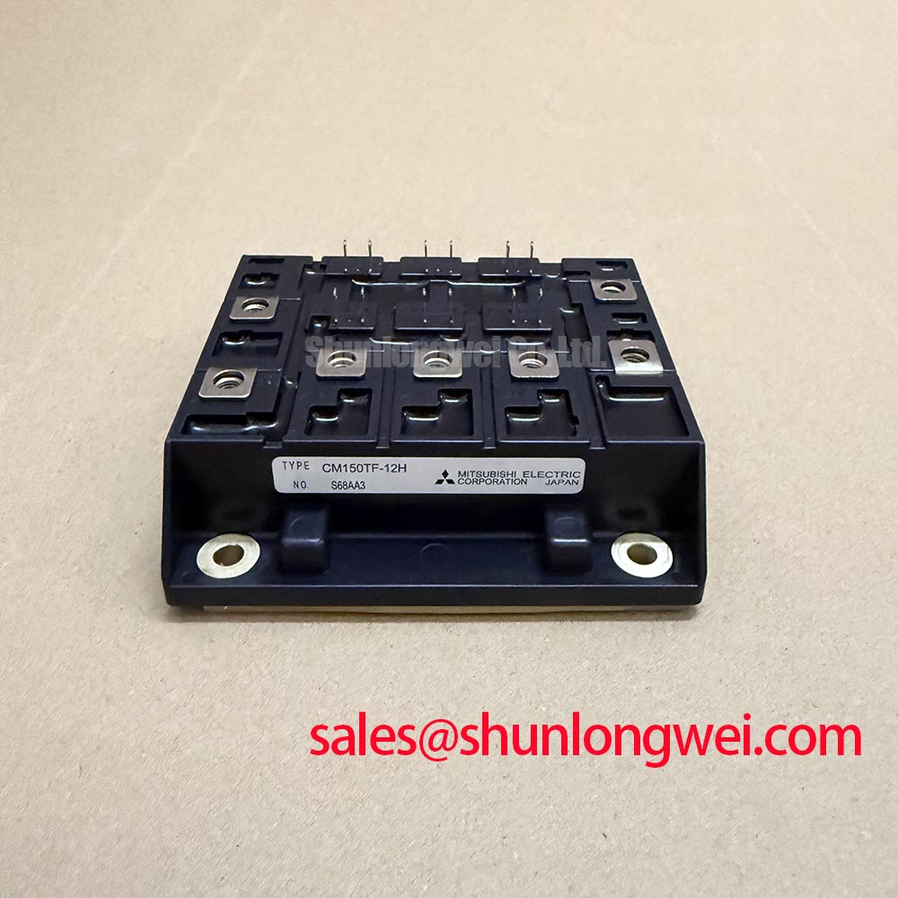
The CM150TF-12H is a Mitsubishi Electric IGBT module rated at 600V and 150A according to the supplied official product information. These two ratings establish the basic electrical identity of the module, but they do not replace a full verification of the original inverter topology, gate-drive arrangement, cooling assembly, bus structure, or terminal assignment before a repair or new integration.
For a product-family reference, Mitsubishi Electric publishes its power-semiconductor portfolio through its Power Semiconductors and High Power Modules resource. System engineers should always reconcile the installed equipment documentation with the exact module marking and circuit requirements.
Before energizing a replacement inverter power stage, verify that the module mounting plane is clean, flat, and free from burrs, dried thermal compound, or foreign particles. A distorted mechanical interface can produce uneven pressure across the module base and complicate thermal evaluation. The module should be held in its intended position while terminal hardware is checked for alignment, avoiding mechanical side loading on power terminals or control connections.
💡 Bench Tip: Keep the module disconnected from stored DC-link energy and use ESD-controlled handling while recording cold-state diode-mode readings as comparative baselines rather than pass or fail values.
High-altitude operation needs a separate system-level risk review. Terrestrial neutron exposure, DC-link operating voltage, switching transient magnitude, enclosure cooling, insulation coordination, and the actual service altitude all interact. No module-specific FIT rate, single-event burnout probability, altitude derating value, or expected operating life is stated in the supplied official parameters for CM150TF-12H. It would therefore be inappropriate to assign a numerical cosmic-ray failure rate or declare a fixed altitude limit for this part.
As a Design Consideration, designers evaluating commercial string inverters or micro-grid energy-storage converters at elevated locations should verify the equipment manufacturer’s altitude and voltage-derating requirements. The review should include measured DC-bus voltage during normal production, regenerative events, grid disturbances, and fault-clearing conditions. Oscilloscope measurements at the device terminals are more informative than relying only on a controller-reported bus-voltage value, because wiring and busbar inductance can create local switching overshoot.
Clearance and creepage requirements are properties of the complete assembly, including the PCB, busbar supports, enclosure pollution degree, conductive contamination risk, and service environment. They are not confirmed by the 600V module rating alone. If an inverter has operated in a demanding environment, inspect nearby gate-drive insulation, DC-link capacitor terminals, snubber connections, and mounting hardware for carbon tracking, looseness, corrosion, or heat discoloration before attributing a fault to the IGBT module.
For broader context on switching-device operation, current paths, and practical test concepts, consult The Ultimate IGBT Knowledge Base. It is useful when establishing a documented incoming-inspection sequence that distinguishes a device-level observation from a system-level reliability conclusion.
CM150TF-12H Thermal-Electrical Optimization: Planar Symmetrical Busbar Geometry for Practical Tuning
The first electrical boundary to verify is the nameplate relationship between the inverter DC link and the module’s 600V rated voltage. The 150A rating is also an Official Specification, but continuous usable current in a finished converter depends on heat-sink performance, airflow, switching conditions, modulation, thermal-interface quality, overload profile, and the protection strategy selected by the equipment designer.
During turn-off, local collector-emitter voltage can rise above the nominal DC-link voltage because the power loop has inductance and current changes rapidly. In engineering terms, the observed peak is influenced by the DC bus plus the product of stray inductance and current slew rate. This is an Engineering Calculation principle, not a published CM150TF-12H overshoot allowance. Designers should measure switching waveforms under their own worst relevant operating conditions and confirm the measured peaks against the inverter’s intended voltage margin.
A compact, symmetrical planar busbar arrangement is commonly assessed to minimize power-loop inductance and suppress turn-off overshoot. The DC-link capacitor connection should be physically close to the commutation loop where the overall equipment layout permits it. Return-current paths deserve the same attention as outgoing conductors. A seemingly short conductor can still create an unfavorable loop if its return path is remote or asymmetric.
Snubber selection is also system-dependent. A capacitor or clamp network that improves a measured transient in one cabinet can introduce unwanted resonant behavior in another arrangement. As a Design Consideration, evaluate snubber effectiveness with measured collector-emitter waveforms, current waveforms, and thermal behavior rather than selecting a value from a generic module-current rule. Check repeatability across operating temperature and representative load transitions.
The supplied data does not specify switching-loss curves, thermal resistance, recommended switching-frequency range, maximum junction temperature, or cooling-air requirement for this exact item. For that reason, frequency-dependent derating or fan-flow values should not be inferred from the 600V and 150A ratings. When integrating the module, designers should obtain the applicable original documentation and validate heat-sink temperature, case temperature, and transient response in the complete power assembly.
Transient Dynamics & Electrical Design: Managing Battery Cycling Swing on CM150TF-12H
Commercial string inverter and micro-grid energy-storage equipment can transfer energy in either direction between battery racks and a DC link, depending on the wider converter topology and control mode. The CM150TF-12H should therefore be assessed within the actual phase-leg or converter arrangement rather than being described as inherently suitable for a specific four-quadrant power-flow function. The circuit schematic, driver logic, anti-parallel current path, protection thresholds, and commanded operating states determine how each module is used.
Rapid battery charge and discharge transitions can create changing current demand and repeated thermal movement in semiconductor assemblies, busbars, capacitors, and mechanical joints. No field-life figures or cycling endurance data are provided in the supplied CM150TF-12H specifications. A responsible maintenance process should focus on measurable conditions: capture DC-link voltage at transition points, compare gate signals between equivalent positions, inspect current-sensor plausibility, and review heat-sink contact integrity.
Gate-loop layout has direct influence on switching behavior. Keep each gate-drive path and its return path close together to reduce loop area, particularly where high current changes can couple noise into the driver. Gate resistance, driver output impedance, isolation arrangement, and local protection circuitry are system-selected variables. The appropriate damping value must be established through controlled testing of the installed design, observing switching voltage, current, ringing, and device temperature.
Miller-related behavior also needs waveform-based verification. During fast collector-voltage movement, capacitively coupled gate current can affect the gate-emitter state. Whether a driver requires a Miller clamp, a negative gate bias strategy, altered damping, or another protection measure depends on the complete gate-driver design and the measured transient environment. These are Design Considerations; they are not official CM150TF-12H requirements stated by the available product parameters.
If switching instability is suspected, do not assume that a single waveform symptom identifies a single cause. Similar ringing can arise from gate-loop impedance, power-loop geometry, probe placement, driver supply disturbance, snubber behavior, or a mismatch between parallel branches. Compare the suspect location against a known-good signal path using appropriate differential voltage and current measurement methods, then correct the verified physical or electrical cause.
CM150TF-12H Operational Boundaries: Evaluating Static and Dynamic Current Distribution AC Limits
Where a converter uses parallel power paths, current distribution must be checked in both steady-state and switching conditions. IGBT conduction characteristics can show a positive temperature coefficient over relevant operating regions, which can support static sharing under controlled conditions. This is a general semiconductor behavior discussion and not a guarantee that any parallel arrangement using CM150TF-12H will share current equally.
Static balance depends on matching conduction paths, thermal environments, mounting conditions, sensing points, and control conditions. Dynamic balance is often more sensitive because differences in gate-drive loop impedance, gate resistance, driver propagation behavior, busbar geometry, and stray inductance can cause one device path to switch earlier or carry a disproportionate transient load. The module’s 150A Official Specification must not be multiplied into a bank-level current claim without testing the finished assembly.
A practical inspection begins by comparing physical symmetry. Confirm that equivalent gate connections use comparable routing and return paths, and that parallel power conductors have equivalent attachment quality. Review torque records where available, inspect for terminal heating evidence, and use calibrated instruments to compare branch current under controlled operating conditions. Any imbalance should be investigated with synchronized voltage and current measurements before modifying gate-drive components.
For a neutral reference point in a higher-current Mitsubishi Electric module family, engineers may compare documented electrical and mechanical requirements with the CM300DXDX1-24A. This link is provided for parameter comparison only. It does not establish interchangeability, a replacement recommendation, identical pin assignment, or suitability for the same inverter assembly.
The supplied CM150TF-12H information confirms a 600V, 150A IGBT module in a module package. Before commissioning, system integrators should verify the original circuit documentation, terminal functions, driver compatibility, measured switching stresses, cooling performance, and protection behavior in the exact equipment being serviced or designed.