Content last revised on July 5, 2026
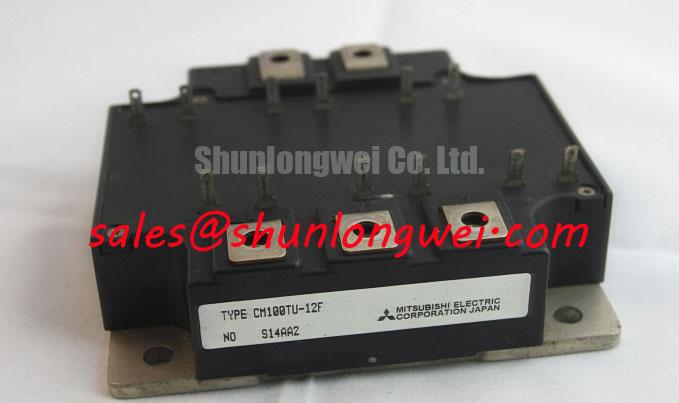
CM100TU-12F: Technical Review of a 600V/100A Dual IGBT Module
Introduction: A Deep Dive into Performance and Efficiency
The Mitsubishi CM100TU-12F is a dual IGBT module engineered to deliver a superior balance of low power loss and robust performance for high-frequency power conversion systems. Leveraging advanced chip technology, it provides a decisive advantage in applications where thermal management and efficiency are paramount. With core specifications of 600V and 100A, this module integrates two IGBTs in a single, thermally efficient package. Its key benefits include significantly reduced conduction losses and optimized switching characteristics. This component directly addresses the engineering challenge of maximizing power density without compromising system reliability. For mid-power motor drives and power supplies prioritizing thermal stability, the CM100TU-12F's low saturation voltage makes it a strategically sound choice.
Key Parameter Overview
Decoding the Specs for Enhanced Switching Performance
The technical specifications of the CM100TU-12F are foundational to its performance in demanding power circuits. The values presented below are extracted from the official datasheet and represent the module's capabilities under specified test conditions. This data is critical for accurate system modeling, thermal design, and gate drive optimization.
| Parameter | Symbol | Condition | Value |
|---|---|---|---|
| Absolute Maximum Ratings (Tj = 25°C unless otherwise noted) | |||
| Collector-Emitter Voltage | VCES | - | 600V |
| Gate-Emitter Voltage | VGES | - | ±20V |
| Collector Current (DC) | IC | TC = 25°C | 100A |
| Collector Current (Pulse) | ICP | - | 200A |
| Collector Power Dissipation | PC | TC = 25°C | 480W |
| Electrical Characteristics (Tj = 25°C unless otherwise noted) | |||
| Collector-Emitter Saturation Voltage | VCE(sat) | IC = 100A, VGE = 15V | 1.70V (Typ) / 2.20V (Max) |
| Gate-Emitter Threshold Voltage | VGE(th) | IC = 10mA, VCE = 10V | 5.5V (Typ) |
| Turn-On Switching Loss | Eon | IC = 100A | 11.0 mJ/pulse (Typ) |
| Turn-Off Switching Loss | Eoff | IC = 100A | 13.0 mJ/pulse (Typ) |
| Diode Forward Voltage | VEC | IE = 100A | 1.70V (Typ) / 2.20V (Max) |
| Thermal Characteristics | |||
| Thermal Resistance (Junction to Case, IGBT) | Rth(j-c)Q | - | 0.26 °C/W (Max) |
| Thermal Resistance (Junction to Case, Diode) | Rth(j-c)D | - | 0.42 °C/W (Max) |
Download the CM100TU-12F datasheet for detailed specifications and performance curves.
Application
Achieving System-Level Benefits in Motor Drives and Power Supplies
The CM100TU-12F is engineered for high-performance applications where efficient power switching is a core requirement. Its architecture provides tangible benefits in industrial systems, particularly in the design of Variable Frequency Drives (VFDs), AC servo drives, and Uninterruptible Power Supplies (UPS).
Consider the design of a compact VFD for a 15 kW AC induction motor. A primary engineering challenge is managing the heat generated by the power stage within a confined enclosure. The CM100TU-12F's low Collector-Emitter Saturation Voltage (VCE(sat)) of 1.70V typical at its nominal current is a critical asset. This parameter can be visualized as the voltage "cost" of having the switch in the 'on' state. A lower VCE(sat) directly translates to lower conduction losses (P_cond = VCE(sat) × IC), which is the dominant source of heat at lower to moderate switching frequencies. By minimizing this loss, engineers can specify a smaller, more cost-effective heatsink, thereby increasing the overall power density of the drive and reducing the bill of materials. The dual configuration further simplifies the inverter leg layout, reducing parasitic inductance and improving electrical performance. For systems requiring higher current handling for larger motors, the related CM150DY-12H offers a 150A capability in a similar voltage class.
Frequently Asked Questions
What is the primary benefit of the F-Series chip technology used in the CM100TU-12F?
The F-Series technology, which represents Mitsubishi's 6th generation CSTBT™ (Carrier Stored Trench Bipolar Transistor) structure, is engineered to optimize the trade-off between conduction loss (VCE(sat)) and switching loss. This results in higher overall energy efficiency, especially in hard-switching applications like Pulse Width Modulation (PWM) inverters, allowing for lower operating temperatures and improved system reliability.
How does the integrated free-wheeling diode's performance affect overall inverter design?
The co-packaged free-wheeling diode (FWD) is optimized for low forward voltage drop (VEC) and soft reverse recovery characteristics. A low VEC reduces power loss during the diode's conduction period. More importantly, a "soft" recovery minimizes voltage overshoots and high-frequency oscillations during the IGBT turn-on event. This reduces electromagnetic interference (EMI) and lessens the stress on the IGBT, potentially simplifying or eliminating the need for external snubber circuits and improving the system's electromagnetic compatibility (EMC).
For inquiries regarding the CM100TU-12F or to discuss your specific power system requirements, please contact our technical support team for further assistance.