
Content last revised on September 16, 2026
PM75RSK060 Specifications and Initial Inspection
With the DC link discharged and isolated, first compare the cold resistance between the accessible power terminals of the installed assembly with the original circuit drawing before fitting PM75RSK060; an unexpected low resistance can point to a failed surrounding snubber, busbar path, or load connection rather than establishing a module fault by itself.
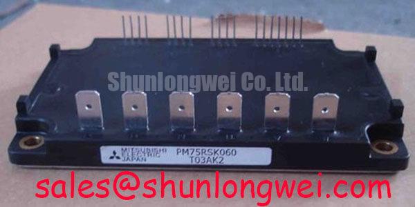
The Mitsubishi Electric PM75RSK060 is an IPM rated at 600 V collector-emitter voltage and 75 A continuous collector current at case temperature 25°C, according to the official specification. Its stated 1.8 V typical collector-emitter saturation voltage under the specified test conditions, 328 W total power dissipation, and junction temperature range from minus 20°C to plus 150°C provide the electrical and thermal boundaries that a repair engineer should verify against the original equipment design. These ratings are relevant when assessing assemblies used in industrial inverter welders or medium frequency induction heating power supplies, subject to confirmation of the original control board, cooling arrangement, and bus structure.
| Official specification | PM75RSK060 value | Integration relevance |
|---|---|---|
| Collector-emitter voltage | 600 V | Official voltage rating for checking the installed DC bus and switching transient margin |
| Continuous collector current | 75 A at case temperature 25°C | Official current condition requiring comparison with the actual cooling condition |
| Collector-emitter saturation voltage | 1.8 V typical under the specified test conditions | Official typical conduction characteristic relevant to thermal loss assessment |
| Total power dissipation | 328 W | Maximum specified power-dissipation value under its datasheet conditions; it depends on the complete heat removal path |
| Operating junction temperature | Minus 20°C to plus 150°C | Official junction operating range, not a substitute for system thermal validation |
Field Diagnostics & Commissioning: Desaturation Detection in PM75RSK060 Topologies
Before returning a repaired inverter welder or induction heating supply to service, inspect the gate drive command, DC bus condition, load path, and fault latch behavior as one chain. A short circuit warning can originate in the power stage, but it can also arise from distorted gate commands, inadequate dead time, an unstable auxiliary supply, an incorrectly seated control connector, or a current feedback circuit that has drifted outside the controller’s expected operating range. Recording the observed gate command and fault sequence before removing the original assembly gives the maintenance team a much stronger reference during recommissioning.
Desaturation monitoring is commonly used in IGBT drive systems to detect an abnormal rise in collector-emitter voltage while a device is commanded on. This is a Design Consideration, not an official built-in protection timing specification for PM75RSK060. The controller designer must validate the protection threshold, blanking arrangement, response time, and shutdown behavior against the actual switching topology and the safe operating limits documented for the original equipment. It is not appropriate to assume a universal detection interval or declare a specific short-circuit withstand capability without the applicable Mitsubishi Electric datasheet and system test evidence.
In practical commissioning, use an isolated measurement method suitable for the energized system and compare waveforms with a known healthy channel where available. Check whether the command signal reaches the driver consistently, whether the gate returns cleanly to its intended off state, and whether the collector voltage behavior corresponds to the commanded switching event. A gate signal that appears normal at the controller but changes at the power assembly can indicate a connector, grounding, isolation, or return path issue. A higher-than-expected collector voltage during conduction may instead indicate a load-side fault, elevated conduction loss, poor thermal contact, or a protection response. The waveform and timing relationship should be assessed together rather than assigning one symptom to one cause.
Two-stage soft turn-off is often considered where a protection circuit must interrupt current in an inductive power loop. The principle is to limit the abruptness of current interruption so that unavoidable loop inductance does not generate an excessive collector voltage transient. The final implementation is system determined: engineers should minimize parasitic loop inductance, retain the original busbar geometry where possible, and verify peak collector voltage against the 600 V official rating during controlled switching tests. Replacing a power module without correcting a damaged snubber, loose busbar, or abnormal commutation path can leave the original stress mechanism in place.
For bootstrap-powered driver arrangements, the charging path and permitted operating sequence should be checked against the original driver documentation. Mitsubishi Electric provides useful general reference material in its DIPIPM™ Bootstrap Circuit Design note. That reference supports driver circuit evaluation but does not replace the PM75RSK060 application documentation or the original equipment schematic.
Assembly Integrity & Layout Architecture: Thermal Capacitance and Heat Sink Evaluation for PM75RSK060
Remove accumulated dust from the heat sink fins and cooling airflow path before drawing conclusions from an overtemperature record. A clean heat sink can still perform poorly if the fan has lost output, the duct has been disturbed, the thermal interface material has aged, or the assembly no longer sits flat against the mounting surface. The PM75RSK060 official 328 W total power dissipation value indicates a thermal boundary under specified conditions; it does not state that the module can dissipate that amount in every enclosure, at every airflow condition, or during every repetitive pulse profile.
For heavy pulsed loading, junction temperature does not follow heat sink temperature instantaneously. The thermal path from silicon to case, thermal interface, heat sink, and ambient environment responds over different time scales. A multi-RC transient thermal model is a useful Engineering Calculation method when the required thermal impedance curves and power loss data are available from authoritative documentation. It allows a system engineer to combine the duty cycle, conduction loss, switching loss, and cooling response to estimate peak junction temperature. Without the complete thermal impedance data for this model and the actual switching loss conditions, a numerical junction temperature calculation should not be presented as a PM75RSK060 factory result.
At the equipment level, inspect terminal faces for discoloration, pitting, looseness, or evidence of movement. Confirm that busbars reach their intended terminal locations without side loading the assembly. Check creepage and clearance against the original equipment drawing and applicable safety requirements, particularly after a repair has introduced replacement busbars, insulating sheets, or wiring ties. A busbar that is mechanically forced into position can create uneven contact pressure and vibration stress even when the electrical connection initially appears satisfactory.
⚠️ Maintenance Note: Periodically monitor terminal contact temperature under representative load and verify that the cooling path remains clear before tightening or reworking energized power connections.
Where the original design uses parallel current paths, static sharing and dynamic sharing require separate attention. IGBT conduction characteristics can support some balancing behavior when devices operate under controlled comparable conditions, but current distribution is also affected by gate drive matching, conductor resistance, connection symmetry, temperature, and switching timing. This is a Design Consideration; PM75RSK060 should not be assumed to share current correctly with another device merely because the nominal current ratings look similar. During an urgent repair, retain the original electrical topology and validate gate and current waveforms before applying full load.
When a broader electrical comparison is required, the CM300DXDX1-24A has different published characteristics and should be evaluated only against the original circuit requirements, mechanical interface, control method, voltage rating, current duty, and thermal design. A part number comparison is not a substitute for a validated replacement decision.
Preventing Spurious Faults: FIT and High Altitude Evaluation for PM75RSK060
Do not calculate a failures-in-time value, a terrestrial neutron-induced failure rate, or a single-event burnout probability for PM75RSK060 from its 600 V rating alone. Such figures require validated device-specific data, environmental assumptions, voltage stress conditions, temperature profile, altitude, mission duration, and an authoritative reliability method. No specific FIT rate, service life, or burnout multiplier should be inferred for this IPM without a published source that supports that exact claim.
At sites above approximately 2000 m, the maintenance team should treat altitude as a system-level Design Consideration. Reduced air density can affect heat removal and external insulation coordination, while the application may impose different bus voltage and switching conditions than a sea-level installation. The correct procedure is to consult the equipment manufacturer’s installation requirements, assess the enclosure and cooling system, then conduct controlled verification of voltage and temperature margins. The module’s official junction range of minus 20°C to plus 150°C defines a device boundary, but it does not establish a complete altitude derating rule for the finished machine.
Spurious fault indications frequently deserve a methodical signal-integrity review before the power assembly is condemned. Check control supply stability, fault-return wiring, shielding continuity where used by the original design, and the separation between sensitive sensing conductors and high-current switching paths. A false trip may indicate common-mode disturbance, a degraded connector, poor grounding continuity, or an issue in a measurement circuit. Oscilloscope comparison against a known good signal path is more reliable than replacing components based on a single fault code.
Industrial inverter welders and induction heating equipment can also include phase-controlled input stages, rectifier sections, or line filtering ahead of the DC bus. Their conduction angle and harmonic behavior are properties of the complete input topology and operating load, not characteristics of PM75RSK060. When investigating repeated DC bus instability, measure the incoming supply, rectifier behavior, capacitor condition, and controlled switching sequence according to the original equipment service procedure. The DC bus must be stable before gate drive or protection behavior can be interpreted confidently.
For structured review of IGBT switching behavior, thermal limits, and power semiconductor terminology, maintenance engineers can consult The Ultimate IGBT Knowledge Base alongside the product documentation and the host equipment schematic.
PM75RSK060 Thermal Electrical Optimization: Optocoupler and Digital Isolator Tuning
When replacing PM75RSK060 in a controlled power assembly, preserve the original gate drive isolation strategy unless the entire driver design is being requalified. Optocoupler-based and digital-isolator-based gate drivers have different propagation characteristics, supply arrangements, common-mode behavior, and fault-reporting methods. Neither technology can be declared inherently suitable for this module without reviewing the original drive circuit, switching frequency, layout, and protection logic. The system integrator should verify the required isolation rating and transient immunity from the original equipment documentation and relevant driver datasheets.
A reliable check begins at the interface between the controller and driver. Confirm that logic commands, enable signals, interlocks, and fault feedback have the expected state during power-up and power-down. Then inspect the gate drive at the power assembly with a measurement technique appropriate for the voltage environment. The purpose is to identify unintended turn-on pulses, missing off commands, unequal timing between switching positions, or abnormal ringing that could disturb the intended gate state. Gate timing and dead time are system-determined values. They should be verified under the actual bus voltage and load conditions to prevent cross-conduction, rather than copied from an unrelated power stage.
Isolation barriers should be evaluated as part of the complete assembly, including PCB spacing, connector selection, cable routing, ground-reference strategy, and enclosure environment. Moisture, condensation, conductive dust, and damaged conformal coating can compromise a system even where the driver device itself meets its stated isolation specification. During preventive maintenance, inspect for moisture paths around low-voltage control connections and ensure that airflow changes have not directed contaminants toward the driver board.
Thermal and electrical checks should be paired during final tuning. The official 1.8 V typical collector-emitter saturation voltage is useful as a conduction-loss reference, but actual heat generation also depends on current waveform, switching conditions, modulation strategy, cooling, and gate-drive behavior. A higher-than-expected case temperature can arise from elevated conduction losses, switching losses, airflow restriction, an imperfect thermal interface, or an external load condition. The appropriate response is to measure each relevant condition and compare it with the original equipment baseline before deciding whether further circuit changes are necessary.
Mitsubishi Electric’s power semiconductor technology resources provide wider context on power device families. Any evaluation of a different power technology remains a system-level exercise requiring validation of voltage, current, drive, protection, thermal interface, and mechanical compatibility.