
Content last revised on October 15, 2026
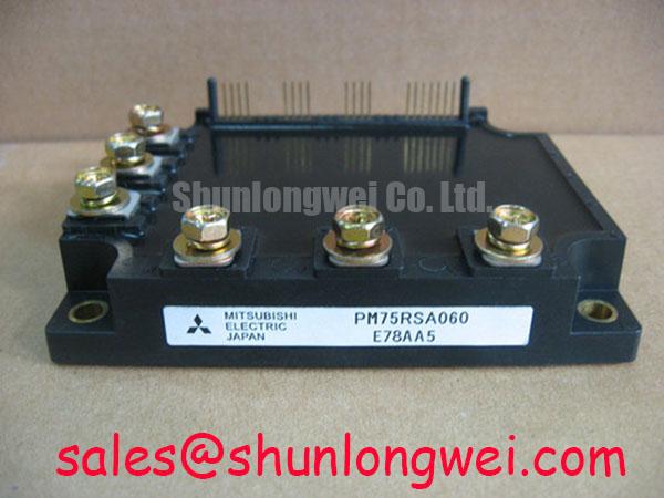
PM75RSA060 Identification and Service Checks
- Isolate the equipment, discharge the DC link using the approved service procedure, and verify absence of voltage before touching PM75RSA060 terminals.
- Compare the module marking and terminal orientation with the equipment parts record and wiring diagram.
- Inspect the heatsink contact surface, mounting hardware, airflow path, and thermal interface for contamination or disturbed assembly.
- Trace control supply returns separately from power conductors before reconnecting the control harness.
PM75RSA060 is a Mitsubishi Electric intelligent power module with specified ratings of 600.0 V and 75.0 A, in a Mitsubishi IPM Module package. These ratings are subject to the datasheet conditions, not universal operating values. For maintenance planning, these identification values belong alongside the equipment schematic, assembly drawing, and operating records, rather than replacing them.
| Product attribute | Specification | Parameter identity |
|---|---|---|
| Model | PM75RSA060 | Product identification |
| Manufacturer | Mitsubishi Electric | Manufacturer identification |
| Voltage rating | 600.0 V | Official Specification |
| Current rating | 75.0 A | Official Specification |
| Package | Mitsubishi IPM Module | Module type |
| Terminal map, rating conditions, dimensions, control interface, and protection characteristics | Consult Datasheet | Assembly and application verification |
Assembly Integrity & Layout Architecture: Implementing Separating Driver Return from Main Current for PM75RSA060
Trace the control reference from the PM75RSA060 connector back to its supply before deciding where the driver return belongs. Design Consideration: a conductor shared with switched load current can develop a transient voltage that shifts the apparent control reference. Separating sensitive control paths from power current paths reduces this coupling, but the actual terminal assignments must follow the module interface drawing. An auxiliary Kelvin emitter pin should not be inferred from the package appearance.
On an IPM assembly, work at the documented external control interface rather than treating the module as a bare IGBT with accessible gate connections. Identify each control input, its reference conductor, and any documented fault connection on the equipment schematic. Keep each signal close to its intended return and avoid routing that pair beside a switching output conductor. Where a harness crosses a power path, assess the coupling and mechanical support together; moving a wire without restoring its restraint can introduce a different service problem.
Engineering Recommendation: investigate suspected reference movement by comparing the control signal at the controller and at the module connector using appropriately rated differential measurement equipment. Record the reference used for each trace. A waveform measured against chassis is not automatically equivalent to the waveform seen by the module input. Disturbance coincident with switching can support a coupling hypothesis, but connector resistance, control supply interruption, and probe pickup also deserve examination before changing the layout.
Mounting quality belongs in the same inspection because a displaced assembly can strain both power terminals and control connectors. Check heatsink flatness and mounting alignment against the assembly requirements, then examine the thermal interface for uneven distribution or contamination. Use the documented tightening sequence and torque for the actual fasteners; generic screw guidance is not a PM75RSA060 mounting specification. Preserve the original insulating barriers and clearances when refitting the harness.
Maintenance Note: Inspect heatsink cleanliness and contact temperature trends at equipment service intervals, and verify airflow before attributing rising temperature to the module. Thermal interface inspection should follow equipment service requirements and observed temperature changes, not an invented replacement interval. After cold storage or a large ambient temperature change, allow the assembly to reach conditions that prevent condensation before energization, following the equipment procedure.
For repair material assessment, a related listing such as PM20CVL060-33 is a comparison reference, not evidence of interchangeability with PM75RSA060. Match the complete terminal arrangement, electrical ratings, control behavior, protection interface, and mounting geometry before considering any alternative. The procurement record should identify the required part number and assembly revision so that a purchasing decision does not depend on a family resemblance.
Potential equipment evaluations include an industrial inverter welder or a medium-frequency induction heating power supply, subject to the actual converter topology and interface requirements. Neither application name establishes compatibility. The useful maintenance question is whether the installed assembly, its controller, and its cooling arrangement match the documented module requirements under the equipment's operating cycle.
Transient Dynamics & Electrical Design: Thermal Cycling Margins in Braking Circuits with PM75RSA060
Locate the braking energy path on the equipment schematic before assigning any braking function to PM75RSA060. Design Consideration: the voltage and current ratings alone do not establish an internal braking transistor, its connections, or its permissible loading. Where the equipment includes a braking chopper, identify the switching device and resistor as a complete circuit, including its sensing, protection, and cooling arrangements.
In a motor converter, deceleration can return stored mechanical energy to the DC link. The braking circuit must accommodate both the energy of the event and the repetition pattern, while keeping bus voltage within the limits of every connected component. Resistor selection therefore involves pulse energy, average dissipation, temperature rise, and enclosure heat rejection. The module's current rating alone does not size that resistor or establish a braking duty cycle.
Review operating records for the conditions that precede a braking fault: repeated short cycles, changes in load, blocked cooling, or an interruption in the resistor circuit. Compare bus voltage, braking command, and temperature behavior during a controlled test approved for the equipment. A rising bus trace can have several causes; correlate it with the actual chopper response and energy path before replacing the power module.
Engineering Recommendation: assess complementary switching interlock at the external command interface, accounting for controller timing, signal propagation, and the module's documented switching behavior. The required dead time is determined by the complete system and operating conditions, not by a generic delay added during repair. Verify that startup, shutdown, and fault recovery cannot inadvertently issue overlapping commands. Where accessible, inspect command timing and power-stage response together rather than relying only on a controller setting.
Thermal cycling deserves attention at the assembly level: changing losses heat the module and heatsink at different rates, while repeated operating cycles change the interface temperature. Trend temperature at reproducible measurement locations and compare equivalent load conditions. After servicing the cooling path, repeat the same operating sequence so that airflow improvement is not confused with a lighter load. These observations support maintenance decisions without assigning an unsupported service-life prediction.
At the DC-link input, distinguish the rectification function from the switching and braking functions. The comparison discussing PMH150CS1D060 can help frame complementary power-stage component assessment, but it does not establish a matched companion for PM75RSA060. Evaluate the actual rectifier, precharge path, capacitor bank, and braking branch as separate elements connected by the same energy bus.
For control and protection terminology, Mitsubishi Electric Power Semiconductors & High-Power Modules provides manufacturer context. Apply the documentation for the exact module and equipment revision when resolving terminal functions or protection behavior; general power-device information does not define the braking capability of this assembly.
Assembly Integrity & Layout Architecture: Implementing High-Frequency Commutation Loop Inductance for PM75RSA060
Follow the short switching current path between the local DC-link capacitor and module power terminals, looking for unnecessary conductor length, enlarged loop area, or disturbed connections. Design Consideration: parasitic inductance produces voltage during rapid current changes, so a mechanically convenient replacement bus connection can alter turn-off stress even when its steady-state resistance appears acceptable.
As an Engineering Calculation, the simplified relationship Vpeak = VDC + Lσ × |di/dt| describes the inductive contribution to turn-off voltage: DC-link voltage and measured current slew magnitude establish how strongly loop inductance affects the peak. It is an approximation, not a PM75RSA060 test result, and ringing, measurement bandwidth, and clamp behavior influence the observed waveform. Establish the permitted peak using the applicable device limits and actual operating conditions rather than prescribing a universal loop-inductance target.
For a redesigned bus connection, closely coupled outgoing and return conductors can reduce loop area. Planar geometry should preserve electrical clearances, mounting access, and mechanical support rather than pursuing compactness alone. During repair, restore the documented busbar arrangement and capacitor connections before introducing layout changes. A displaced local capacitor connection or loosened joint can change the commutation path enough to make previous waveform records unrepresentative.
Engineering Recommendation: assess a snubber from the measured ringing and switching conditions, including its pulse loading, dissipation, and connection inductance. If the equipment uses a metal oxide varistor, examine its specified voltage behavior and energy duty alongside the snubber and upstream protection. Neither device should be assumed to absorb every repetitive switching transient. Component placement and the actual current path determine whether the protective network intercepts the stress where intended.
Diode reverse recovery can also influence commutation current and ringing. Treat recovery softness as a characteristic requiring device test conditions, not as a number inferred from the module's voltage class. When comparing waveforms, preserve load current, temperature, bus voltage, and measurement setup. A change in radiated disturbance warrants investigation of the complete assembly; it does not establish that the module itself has or lacks an equipment-level EMC certification.
Miller coupling provides another reason to keep control references stable, but reverse transfer capacitance and Miller plateau charge are different quantities and should not be substituted for one another. Do not add external negative gate bias or an active gate clamp to the PM75RSA060 control inputs as though they were bare gate terminals. Any protection modification belongs at the documented interface and requires validation against its permitted input behavior.
The article Unlocking Efficiency in Industrial Drives offers broader switching-loss and margin context, not a PM75RSA060 acceptance standard or evidence that this module uses that technology. The Mitsubishi Electric Global Semiconductor Device Technologies portal provides manufacturer background for distinguishing device families. For the repaired assembly, retain bus-voltage and switching records, document probe locations, and compare the restored layout under the equipment's approved operating test before returning it to service.