
Content last revised on October 28, 2026
CM400ST-24S1 Identification and Service Checks
- Isolate the DC link, verify discharge with suitable test equipment, and disconnect the driver before checking terminal resistance.
- Compare collector-to-emitter and gate-to-emitter measurements with the service procedure and a known-good assembly under the same conditions.
- Inspect the mounting surface, terminal hardware, insulation barriers, and driver connector before disturbing the original wiring arrangement.
- Match the complete CM400ST-24S1 designation and terminal drawing to the equipment documentation before authorizing installation.
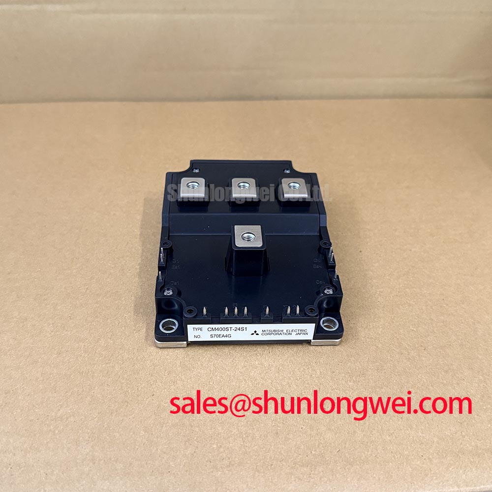
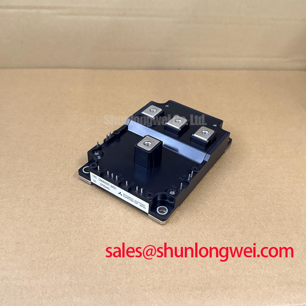
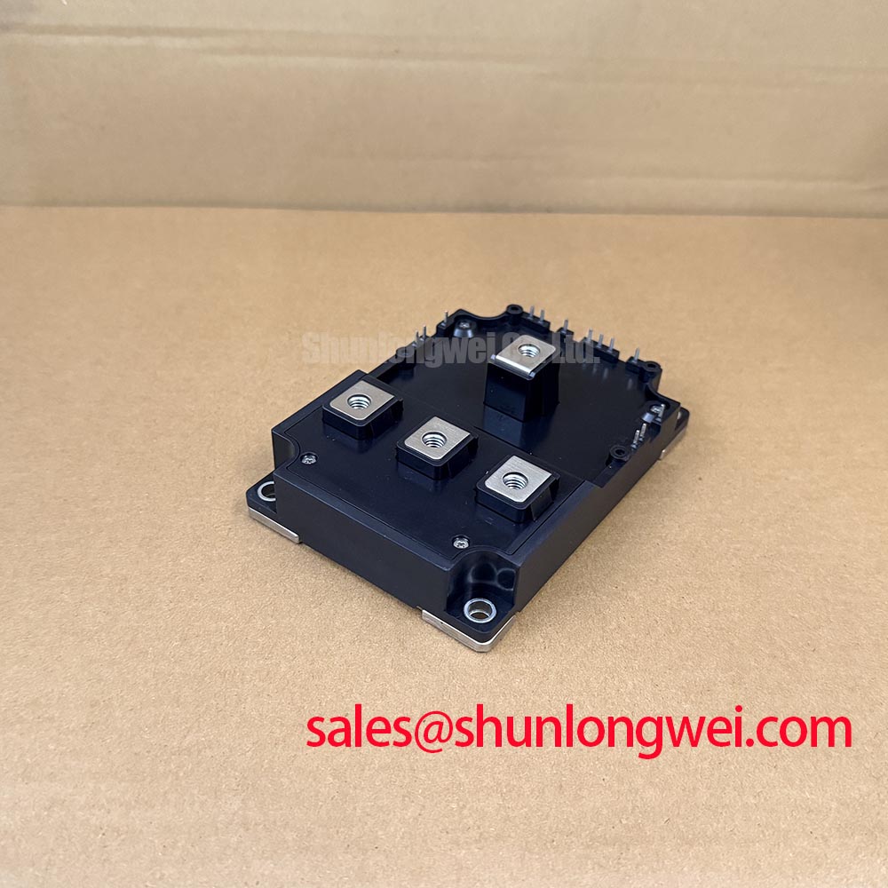
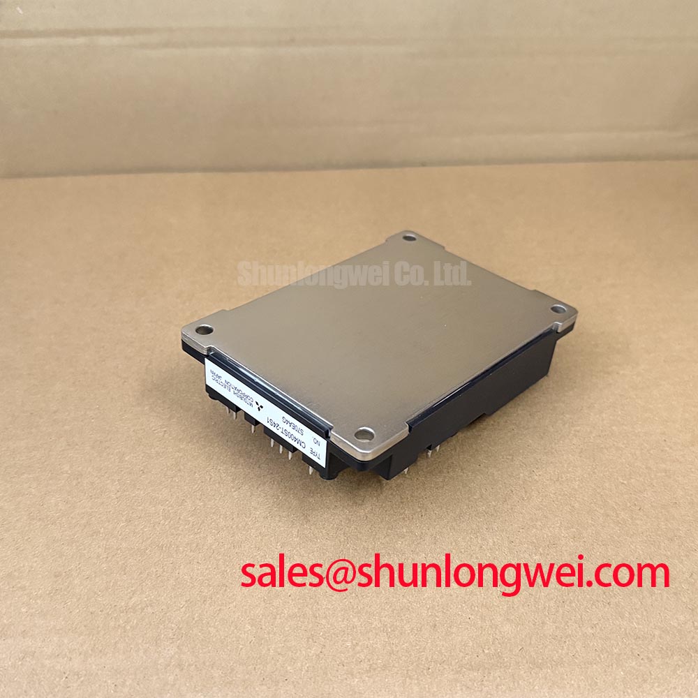
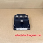
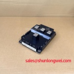
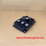
The Mitsubishi Electric CM400ST-24S1 is identified here as an IGBT module with a supplied current rating of 400.0 A and a Module package classification. Replacement assessment should connect those identifiers to the original circuit diagram, mechanical drawing, and gate-driver requirements rather than rely on the model name alone.
Specification checkpoint: Confirm the collector-emitter blocking voltage rating against the manufacturer datasheet before energization. Terminal assignments, current-rating conditions, gate limits, dimensions, and mounting requirements also require the matching datasheet.
Transient Dynamics & Electrical Design: Gate-to-Emitter Loop Routing on CM400ST-24S1
Trace the gate-driver return to the terminal identified as emitter in the module drawing, rather than interpreting an equipment-board “S” marking as a semiconductor terminal definition. IGBT control voltage is gate-to-emitter, not gate-to-source. A board label alone does not establish an auxiliary emitter connection or confirm that this module provides a dedicated Kelvin return.
Design Consideration: Where the documented terminal arrangement provides a separate control return, route the outgoing gate connection and its return together, away from the main switching-current path. Shared emitter-path inductance can introduce voltage into the driver reference during current transitions. Separating the control loop from the load-current loop reduces that coupling, but waveform measurements must establish whether the installed arrangement achieves the required behavior.
Inspect cable routing before changing gate resistance. A return wire diverted around a busbar, a replacement harness with a larger loop, or a connector moved during repair can change the measured switching behavior. Compare the physical routing with the approved assembly drawing. Preserve insulation spacing at terminal edges and mounting hardware according to the equipment’s voltage, environment, and insulation requirements; no universal clearance follows from the package description.
Measure gate-to-emitter voltage with a suitable differential probe connected close to the documented control terminals. Keep the measurement loop compact and distinguish actual gate movement from probe pickup. If ringing changes substantially when the probe leads move, investigate the measurement arrangement before modifying the driver. Correlate the gate trace with collector-emitter voltage and load current rather than treating a single oscillating trace as proof of module damage.
For repair-material comparisons, the CM150RX1-24A provides a separate Mitsubishi product reference, not an established replacement for CM400ST-24S1. Any substitution assessment must compare circuit configuration, electrical limits, terminal geometry, thermal interface, and driver compatibility independently.
Transient Dynamics & Electrical Design: Preventing Spurious Power-Up Shoot-Through on CM400ST-24S1
Capture the driver supply, enable signal, fault output, and gate-to-emitter voltage through startup before reconnecting the complete power stage. The useful question is whether the gate remains controlled while auxiliary supplies rise, settle, or disappear. A steady-state supply measurement cannot reveal a brief startup interval in which the output stage is not yet controlling the gate.
Design Consideration: The equipment control sequence should establish the driver’s specified off-state behavior and undervoltage protection before permitting switching or applying the DC link through the approved startup sequence. If the original driver uses negative gate bias, verify that bias against its documented operating requirements and the module’s gate limits. A generic negative-bias range is not an installation specification for this part.
Check the terminal map at both ends of the harness, including enable polarity and fault-reset behavior. Connector fit does not prove electrical compatibility. During shutdown and auxiliary-supply interruption, observe whether the driver maintains a defined gate state until the power circuit reaches the equipment’s safe condition. Evaluate restart behavior as well as the first startup, particularly where the control supply and DC link decay at different rates.
Design Consideration: Dead time must accommodate the actual switching behavior, driver propagation mismatch, and operating conditions of the complete bridge. Excessive overlap can produce cross-conduction, while excessive dead time can alter diode conduction and output behavior. Determine the setting through the approved system validation procedure rather than assigning a universal delay from the module current rating.
At the power terminals, inspect displaced insulating barriers, busbar alignment, and fastening arrangements disturbed during service. Use the specified hardware and tightening procedure without forcing a misaligned busbar into position. Field Alert: Verify DC-link discharge before reconnecting gate wiring, and apply only the documented terminal and mounting tightening requirements.
A multi-megawatt offshore or onshore wind-turbine full-scale converter is a potential compatibility-assessment context, not an established application approval for this module. Its bridge position, protection sequence, cooling arrangement, and electrical stresses would need equipment-specific evaluation before replacement acceptance.
CM400ST-24S1 Thermal-Electrical Optimization: Practical Tuning to Reduce High-di/dt Gate-Loop Disturbances
Compare the gate waveform at the driver output with the waveform at the module’s documented gate and emitter connections during controlled switching tests. A difference between those measurements can expose wiring impedance, reference movement, or connector effects that remain hidden when probing only the driver board. Establish the connection diagram before interpreting either trace.
Design Consideration: Adjustments to gate damping should balance switching loss, voltage overshoot, and unintended gate movement under the actual load conditions. Change one controlled variable at a time and retain comparable captures. A quieter waveform does not by itself demonstrate lower total loss, and a faster edge does not establish better system performance.
Freewheeling-path behavior also affects commutation. Reverse-recovery current can contribute to switching-current peaks and excite parasitic ringing, so inspect the complementary current path when evaluating a disturbed turn-on waveform. Do not assign a recovery-softness factor to CM400ST-24S1 without the relevant manufacturer characterization. Likewise, system emissions require equipment-level assessment rather than an EMC claim attached to an individual module.
Where the original circuit includes a snubber or MOV network, check its connections and documented component characteristics before changing gate-drive settings. Design Consideration: An absorber’s clamp behavior, pulse capability, and connection inductance must be coordinated with the measured transient and semiconductor limits. Adding suppression hardware without that assessment can redistribute stress instead of resolving its source.
The system schematic should also identify the role of every associated power module. The CM800HA-28H is a separate power-module reference for comparative architecture review; its presence in a product range does not establish a rectifier function, a complementary bridge pairing, or compatibility with CM400ST-24S1.
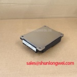
After electrical checks, inspect baseplate contact, heatsink condition, and the thermal interface using the equipment assembly procedure. Uneven contact can complicate interpretation of temperature differences. Where devices operate in parallel, assess both current-path symmetry and driver timing; a generic positive-temperature-coefficient argument cannot establish static or dynamic current sharing for this assembly.
Assembly Integrity & Layout Architecture: Isolated DC-DC Gate-Driver Power Supply Sizing for CM400ST-24S1
Check the isolated driver supply against the installed driver’s loading and startup behavior, including rail movement during repetitive switching. Supply selection depends on gate-charge demand, switching activity, driver consumption, and the converter’s operating conditions. The module’s supplied current rating is not a basis for assigning isolated-supply wattage.
Design Consideration: Isolation withstand, working voltage, insulation classification, and common-mode transient immunity describe different aspects of the driver assembly. Evaluate each against its own manufacturer documentation and the equipment’s applicable safety requirements. A withstand-test value alone does not demonstrate reinforced insulation, and an isolator’s CMTI specification does not establish immunity of the entire gate-drive board.
Inspect the barrier physically for conductive debris, damaged slots, displaced wiring, and mounting hardware that crosses the intended separation. During controlled tests, monitor driver outputs and fault signals alongside switching-node transitions to investigate unexpected pulses. Use appropriately rated measurement equipment without creating an unintended connection across the isolation barrier.
The operating principles described in Buck Converter Step-Down Voltage Regulation help explain switched-inductor current paths, while Zero-Voltage Switching Resonant Converters introduces resonant switching concepts. These are general topology references, not evidence that this module uses either operating mode or achieves particular switching losses.
For broader technology context, Unlocking Efficiency in Industrial Drives discusses another IGBT technology platform; it is not Mitsubishi documentation or a characterization source for CM400ST-24S1. Complete the repair record with the approved terminal map, supply-sequencing captures, gate waveforms, fastening checks, and thermal-interface inspection so the next service intervention can reproduce the installed configuration.