Content last revised on October 14, 2026
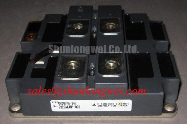
Transient Dynamics & Electrical Design: High dv/dt Cross-Conduction Shoot-Through on CM800HA-28H
I place the gate-voltage measurement reference at the module’s emitter connection when investigating unintended turn-on, rather than assuming the driver-board waveform represents the voltage reaching the device. For the CM800HA-28H, simultaneous observation of collector voltage, gate voltage, and branch current helps distinguish capacitive gate disturbance from commanded switching overlap. The measurement arrangement must be appropriate for the circuit voltage and common-mode transient environment; probe placement itself can change the apparent disturbance.
Design Consideration: collector-voltage transitions can couple displacement current into the gate circuit through collector-to-gate capacitance. A long gate return path or excessive turn-off path impedance can let that current raise the gate potential. Designers should evaluate an active Miller clamp close to the device connection, with a short return path that does not share avoidable inductance with the main power current. Clamp activation timing and current-handling capability belong to the selected driver design, not to the module’s voltage and current ratings.
Negative off-state bias is another circuit-level option, but its magnitude must follow the permitted gate-voltage limits and the driver’s operating envelope. The Evolution of Negative Off-Bias Gate Drive Circuits provides supporting discussion for assessing the turn-off path. During testing, inspect the actual gate excursion, including undershoot, rather than treating a negative auxiliary supply as proof that unwanted turn-on has been suppressed.
Engineering Recommendation: assess the optocoupler or digital isolator’s common-mode transient immunity against measured switching disturbances. Compare the logic signal before isolation with the driver output afterward; an input pulse, isolation upset, and Miller-induced gate excursion require different corrective actions. Keep control routing separated from switching-node conductors while preserving the insulation distances required by the equipment’s insulation coordination.
Pro Tip: Keep commutation paths geometrically balanced to reduce unequal inductive overshoot, then validate the resulting voltage margin with system-representative double-pulse measurements.
For repair sourcing, CM1200HA-34H can enter a comparative assessment, but it is not a confirmed interchangeable replacement. Consult Datasheet for terminal arrangement, mounting dimensions, gate limits, switching characteristics, and thermal interfaces before accepting a substitution; higher headline ratings alone do not establish compatibility.
Transient Dynamics & Electrical Design: Cosmic Ray Robustness and Voltage Derating on CM800HA-28H
Separate the intended blocking-voltage envelope from measured switching peaks when assessing voltage derating for the CM800HA-28H. Its 1400 V rating is an official electrical specification, not a documented cosmic-ray immunity level. The assessment should include the highest sustained DC-link voltage, repetitive overshoot, and abnormal energy-return conditions, with each condition evaluated against the applicable device limits.
Design Consideration: terrestrial neutron exposure can be relevant to single-event burnout assessment in power semiconductors, and installation altitude belongs in an application-specific reliability review. A numerical FIT estimate requires authoritative device-specific characterization and a defined exposure model. Neither an altitude threshold nor a failure-rate reduction can be assigned to this module from its blocking-voltage rating. Reliability requirements should therefore be translated into a supplier-supported operating-voltage assessment rather than an assumed universal derating percentage.
Keep this assessment distinct from short-circuit protection. Desaturation detection monitors abnormal collector-emitter voltage during commanded conduction; it does not establish immunity to single-event burnout. Engineering Recommendation: evaluate detection blanking, propagation delay, driver response, and current interruption as a complete sequence. Select timing against documented short-circuit behavior and measured switching noise, rather than imposing an arbitrary response time that could cause nuisance trips or leave excessive fault energy.
A staged soft turn-off can help manage the trade-off between rapid fault-current reduction and inductive overvoltage. Its effectiveness depends on the driver circuit, commutation inductance, and fault-current trajectory. Record collector voltage and current throughout the protective transition, including any gate rebound. Protection validation should also include the behavior after a latched fault, especially whether subsequent commands remain inhibited.
For upstream semiconductor fuse coordination, compare the fuse’s clearing characteristics and let-through I²t with documented withstand information for the complete fault path. A fuse cannot be assumed to prevent module rupture solely because its continuous current rating appears suitable. Available fault current, circuit inductance, DC interruption capability, and stored capacitor energy influence the outcome. If regenerative operation raises the DC link, assess the system’s energy-absorption provision separately; a braking chopper and resistor require their own voltage, pulse-energy, and thermal evaluation.
CM800HA-28H Operational Boundaries: Evaluating Thermal Feedback Limits
Measure current distribution and thermal conditions together when evaluating parallel operation, because equal gate commands do not establish equal loading. The 800 A official current rating should enter the assessment alongside the manufacturer’s rating conditions, cooling arrangement, and operating waveforms. It should not be converted directly into an allowable continuous equipment current without a thermal evaluation.
Design Consideration: a positive temperature coefficient of collector-emitter saturation voltage can assist static current sharing over operating regions where that behavior is established. It must not be assumed across the full current and temperature range of the CM800HA-28H. Use the applicable characteristic curves to identify the relevant region, then compare conducting voltage and branch current under matched operating conditions. Unequal terminal resistance or cooling can obscure the semiconductor’s contribution to current distribution.
Dynamic balance requires a separate examination of gate wiring, driver delays, and power-path geometry. Designers should consider comparable gate-loop impedances and avoid routing arrangements that expose one branch to greater switching-node coupling. During testing, compare current rise, current fall, and transient collector voltage between branches. A temperature difference alone does not identify whether the imbalance originates in conduction losses, switching losses, or the cooling interface.
Engineering Recommendation: inspect heatsink contact condition, mounting flatness, and the thermal interface before interpreting a persistent hot spot as an electrical defect. Apply the specified assembly procedure rather than borrowing torque or interface-thickness values from another module. Around the power terminals, preserve creepage and clearance according to system voltage, pollution conditions, insulating materials, and the applicable equipment requirements; no universal spacing follows from the module rating.
A utility-scale centralized battery energy storage PCS is one potential compatibility assessment context, subject to topology, operating voltage, cooling, and protection validation. Background on Lithium Iron Phosphate (LiFePO4) Battery Storage Chemistries and Battery Management System (BMS) Architecture in Energy Storage helps distinguish battery-side operating constraints from converter requirements. These references do not establish module qualification. When reviewing adjacent conversion stages, assess CM350DU-5F through its own device data and circuit role, not as an automatically compatible rectifier or companion.
CM800HA-28H Circuit Protection & Reliability: Preventing Spurious Power-Up Shoot-Through
Capture auxiliary-supply startup, driver enable, gate voltage, and DC-link energization on a common timebase to identify an unsafe power-up interval. A controller’s disabled command does not by itself demonstrate that the CM800HA-28H gate remains controlled while the driver supply is rising. Check the output state through undervoltage lockout, supply recovery, and any controller reset.
Design Consideration: where negative off-state bias is used, the sequencing logic should recognize when that rail and the driver’s operating supply are valid before permitting switching. The gate must also have a defined off-state path while active driver circuitry is unavailable. Interlock behavior should be assessed at the module connection, including loss of one auxiliary rail, interrupted enable signals, and uneven recovery between complementary switches.
Engineering Recommendation: exercise startup and shutdown under controlled, appropriately protected test conditions before full-power operation. Observe whether a collapsing auxiliary supply releases the gate, whether the driver produces a transient output pulse, and whether fault latching survives a reset. Set sequencing delays from measured settling behavior and component requirements rather than assigning a generic waiting period.
Dead-time generation and driver readiness should be evaluated independently. Correct steady-state dead time cannot compensate for an undefined output during startup, and a stable auxiliary supply cannot correct overlapping switching commands. Check both command paths for consistent inhibition and confirm that the protection circuit retains authority during controller initialization.
After a driver-board or module replacement, repeat the supply-sequencing capture with the installed wiring and gate connections. Accept the assembly only when startup, brownout, shutdown, and fault recovery produce the intended off-state behavior without an unintended gate pulse or complementary-switch overlap.