Content last revised on October 29, 2026
CM800HA-24H Ratings and Initial Inspection
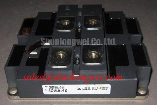
With the traction inverter isolated, inspect the main terminals, gate wiring, and busbar joints before applying a replacement module. Confirm that the installed device is marked CM800HA-24H and compare the inverter’s electrical design limits with the module’s 1200 V collector-emitter voltage and 800 A DC collector current ratings under the specified datasheet conditions. Mitsubishi Electric specifies a typical 2.1 V collector-emitter saturation voltage under its stated test conditions, a maximum collector power dissipation of 4300 W under the specified thermal conditions, an isolation voltage of 2500 V AC for 1 minute, and a junction temperature range of −40 to +150 °C.
These figures identify the CM800HA-24H as a high-current Mitsubishi Electric IGBT module for demanding converter stages, including engineering evaluation in high-speed rail and heavy freight locomotive traction inverters. The ratings are specification values; the usable operating point remains dependent on switching frequency, cooling, gate-drive conditions, commutation behavior, busbar construction, and the thermal design of the complete power stage.
| Manufacturer | Mitsubishi Electric |
| Part number | CM800HA-24H |
| Collector-emitter voltage | 1200 V |
| Continuous collector current | 800 A DC under the specified datasheet conditions |
| Typical collector-emitter saturation voltage | 2.1 V under the specified test conditions |
| Maximum collector power dissipation | 4300 W under the specified thermal conditions |
| Isolation voltage | 2500 V AC for 1 minute |
| Junction temperature range | −40 to +150 °C |
Preventing Spurious Faults: PCB Gate Loop Layout Symmetry Guidelines for CM800HA-24H
Separate the auxiliary emitter return used by the gate driver from the high-current emitter path before investigating intermittent gate faults. Shared copper can couple the power-emitter voltage change into the driver reference, producing an apparent gate disturbance even when the controller command is stable. The CM800HA-24H should therefore be connected with a gate loop that is physically compact, symmetrical, and independent of the main commutation current path wherever the terminal arrangement permits.
As a Design Consideration, route the gate signal and its return as a closely coupled pair rather than allowing the return to travel through a high-current copper region. Keep the driver reference connection away from collector and emitter switching edges, and avoid routing sensitive gate traces alongside the commutation loop. The practical objective is to reduce mutual coupling and prevent the auxiliary emitter reference from moving with the power current.
When several modules operate in parallel, use equivalent gate-loop geometry for each device. Differences in trace length, copper width, connector placement, or return path impedance can create unequal switching timing. A module that turns on or off earlier may carry a disproportionate transient current even when static current sharing appears acceptable. Gate resistors, driver outputs, and local decoupling should be arranged so that the electrical path is as consistent as the mechanical layout allows.
During field troubleshooting, compare the gate-to-emitter waveform directly at the module terminals rather than at the driver board. A waveform that looks clean at the driver output but shows ringing at the module indicates that the interconnect and reference path require attention. Check the auxiliary emitter connection for loose hardware, contamination, cracked solder joints, and unintended current sharing with the main emitter conductor. If the fault appears only during high-current switching, inspect the power-return geometry before changing controller settings.
Pro Tip: Keep the laminated busbar and gate-drive return physically coordinated, then verify turn-off overshoot and gate stability with appropriately rated isolated or differential probing during controlled switching tests.
Benchtop Waveform Tuning: Mitigating Stress via Torque Reaction Absorption and Preventing Terminal Damage on CM800HA-24H
Mechanical stress at the main power terminals can become an electrical reliability problem when screw loading, washer tension, and busbar alignment force the internal copper connections to absorb assembly movement. Before waveform tuning, fit the module on a flat thermal interface and align the busbar without using the terminal screws to pull misaligned conductors into position. The terminal hardware should clamp the intended stack, not act as a lever for correcting enclosure or busbar errors.
As a Design Consideration, confirm thread engagement, washer seating, and conductor flatness during installation. Thermal cycling and vibration can relax an uneven joint, while excessive mechanical reaction can transfer stress into internal copper-bonded regions. The correct tightening method, fastener arrangement, and heatsink interface should follow the applicable Mitsubishi Electric mechanical documentation and the equipment manufacturer’s assembly process.
Parallel static current sharing benefits from symmetrical collector and emitter busbar paths. The temperature dependence of IGBT saturation voltage must be assessed at the intended operating point; it should not be assumed to provide automatic current balancing. It does not replace matched impedance, equal thermal coupling, or controlled gate timing. Measure the voltage drop and temperature behavior of each parallel path under the intended load profile. A small difference in connection resistance can alter current distribution before the semiconductor temperature response becomes visible.
For a benchtop check, first confirm that each module is seated without rocking and that the busbar stack remains relaxed before final tightening. Then observe collector-emitter voltage, gate-to-emitter voltage, and current sharing during a limited-energy pulse. If one branch shows a different switching edge, investigate busbar symmetry, gate-loop impedance, and terminal contact condition as separate variables. Do not treat a mechanical correction as a substitute for electrical balancing.
The CM800HA-24H may be evaluated alongside other Mitsubishi Electric power modules where the topology, voltage class, current requirement, mechanical interface, and gate-drive conditions are compatible. The CM450DX-24S1 is a related device for neutral cross-reference review, not an automatic replacement. Any substitution requires comparison of circuit configuration, thermal path, terminal arrangement, switching characteristics, and protection settings.
CM800HA-24H Thermal-Electrical Optimization: Managing Commutation Turn-Off Voltage Overshoot
Start turn-off stress analysis at the commutation loop, where stray inductance produces an additional voltage as the switching current falls. Separately, the antiparallel freewheeling diode can produce a reverse-recovery current peak and a steep current transition when the opposing IGBT turns on. That event may produce voltage overshoot across the recovering diode, increase electromagnetic emissions, and add losses in the power stage.
As a Design Consideration, minimize the physical area of the high-current commutation loop and keep the forward and return conductors closely coupled. A laminated busbar can reduce parasitic inductive effects when its geometry is correctly matched to the switching topology. The final clearance, conductor thickness, insulation system, and mechanical stack are system-design decisions; transient performance should be validated by measuring the actual peak voltage at the module terminals.
RC snubber selection should follow measured ringing frequency, energy dissipation, capacitor pulse capability, and resistor thermal loading. The snubber is not a universal cure for poor busbar geometry. If the ringing changes substantially with probe position or connection length, correct the measurement arrangement and layout before selecting component values. A turn-on gate resistor can also be considered as a tuning element to moderate current rise during diode commutation, while turn-off gate resistance affects IGBT turn-off overshoot. Their values must be established from the driver capability, gate charge behavior, switching loss, and thermal test results.
When a traction inverter shows abnormal voltage spikes, compare the waveform under matched load and switching conditions. Record whether the event occurs during diode commutation, hard switching, or a control transition. Review the gate signal for Miller-induced movement and check that the driver has sufficient source and sink capability. The CM35MX-24A can be included in a separate power-module comparison, but its circuit configuration, ratings, and application suitability must be assessed independently.
Thermal evaluation should include the measured saturation-voltage behavior, switching loss, heatsink temperature distribution, and interface condition. The specified 4300 W maximum collector power dissipation is a component specification and should not be interpreted as a guaranteed operating point without the corresponding case temperature, cooling method, duty cycle, and electrical loss calculation.
Benchtop Waveform Tuning: Common-Mode Transient Immunity in Harsh Industrial Environments
Verify the complete isolation barrier between the control electronics and the high-voltage switching section before attributing a false trigger to the CM800HA-24H. The module’s specified isolation rating is 2500 V AC for 1 minute; this is an isolation withstand specification, not a confirmation of a particular gate-driver CMTI rating. Driver isolation, creepage, clearance, common-mode current paths, and enclosure bonding must be evaluated as a complete system.
Do not assign a CMTI value or reinforced-barrier performance to the IGBT module unless it is explicitly stated in the relevant module documentation. As an Engineering Recommendation, select isolation components and layout practices appropriate to the measured switching transient, then verify that no short-duration gate pulse appears during the collector voltage transition. Probe placement, measurement-system isolation, fiber or digital-isolator behavior, and local driver decoupling all influence the result.
Common-mode current can return through heatsinks, shields, mounting hardware, cable screens, and control-board capacitance. Keep the high dv/dt switching region separated from low-level control references, and define the intended chassis and shield return rather than allowing current to find an uncontrolled path. The Power Electronics Masterclass provides additional system-level reference material for power-loop construction, transient evaluation, and reliability-oriented bench testing.
For component and topology comparisons, consult Mitsubishi Electric’s SiC Power Modules and SBDs information and the NX-Series IGBT Module material. These references can help engineers frame switching-speed, isolation, and thermal questions without treating another product family as a direct substitute for the CM800HA-24H.
Safety Interlock Note: Remove DC-link energy and verify the discharge state before connecting, disconnecting, or attaching probes to the module gate circuit. Energized waveform testing requires appropriately rated probes and established high-voltage test procedures.