Content last revised on October 2, 2026
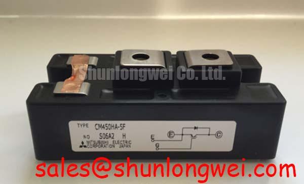
Assembly Integrity and Busbar Layout for CM350DU-5F
| Model | CM350DU-5F |
|---|---|
| Manufacturer | Mitsubishi Electric |
| Product category and package | IGBT Module |
| Rated voltage | 600 V (Official Specification) |
| Rated current | 350 A (Official Specification) |
Measure the discharged DC bus and check cold resistance between the module’s power terminals before disturbing the busbar assembly. Record the readings and compare them with an unaffected phase or service record where available; an unusual reading calls for circuit isolation, not an immediate verdict on the module. Inspect terminal seating, busbar alignment and the mounting surface while the connections are accessible.
For CM350DU-5F, the stated 600 V and 350 A ratings are Official Specifications, not measurements of the installed assembly. A compact industrial inverter or high-speed CNC spindle drive is a possible application to evaluate, subject to its schematic, mechanical fit and operating conditions. In a rectifier-fed drive, trace the path from the incoming supply through rectification and the DC link to the switching stage. The CM30TF-12E is a separate module worth examining only when the equipment schematic calls for a compatible device in that path; its function cannot be inferred from proximity to this IGBT module.
Design Consideration: Keep opposing DC-link current paths close and geometrically balanced to reduce loop inductance. During turn-off, bus voltage and the voltage induced by changing current both contribute to the peak seen at the switch. Place any snubber according to the actual commutation path, then measure the peak at the module terminals during controlled switching. Busbar spacing, clearance and snubber selection must follow the equipment’s insulation design and measured waveforms, rather than a generic layout target.
Benchtop Gate Waveforms and Turn-Off Stress
Probe gate-to-emitter voltage at the module connections during a controlled switching test, and compare the waveform with collector-to-emitter voltage at turn-off. Ringing or an unexpected gate rise warrants inspection of the driver return route, connector contact and power-loop geometry before changing driver components. Use an appropriate differential measurement arrangement so the probe does not introduce a new return path.
Engineering Recommendation: Route the gate-drive return separately from the main current path where the documented terminal arrangement permits it. Do not assume CM350DU-5F has a dedicated Kelvin emitter terminal without checking the connection drawing for the unit being installed. A negative off-state bias, if used by the existing driver, should be evaluated against its driver documentation and measured gate waveform; it is not an unstated requirement of the module.
Keep the film snubber’s connection to the switching loop short where a snubber is present. Change one layout or drive variable at a time and repeat the turn-off capture under controlled conditions. This makes it easier to distinguish busbar-induced overshoot from gate-loop oscillation. For a broader comparison of switching-device trade-offs, Wide Bandgap Revolution provides context, but the installed module’s limits and the measured DC-link transient govern this repair.
Current Balance, Protection and Replacement Fit
Compare current waveforms in parallel switching paths before attributing an intermittent trip to one module. Unequal path resistance, gate wiring or thermal contact can alter sharing, and a cold resistance check alone cannot establish dynamic balance. Use the equipment schematic to identify which paths are genuinely parallel, then inspect their connections and compare waveforms under the same test conditions.
Design Consideration: Temperature-dependent conduction behaviour may assist static sharing in an appropriate operating region, but it does not establish balanced turn-on or turn-off. Symmetrical bus and gate paths still need measurement. If the driver reports a desaturation fault, capture the fault signal, gate waveform and collector-to-emitter response together. Check how the installed driver implements detection and soft turn-off before judging short-circuit protection; no short-circuit safe operating area or protection timing is specified here for this module.
For a cross-model assessment, CM150DU-34KA can be examined against the original connection drawing, ratings, gate-drive requirements and mounting arrangement. The shared model family does not establish interchangeability. ⚠️ Field Alert: Isolate and discharge the DC link before loosening module terminals or reconnecting gate wiring.
Field Diagnostics During DC-Bus and Motor Commissioning
Capture DC-link voltage during commanded deceleration and correlate any surge with the drive’s braking command and fault log. A rising bus voltage does not, by itself, identify a failed CM350DU-5F: inspect the braking path shown on the equipment schematic, its control signal, resistor connections and the energy path available during deceleration. Size or assess braking hardware from the drive and motor duty, not from this module’s voltage and current ratings alone.
Where phase-controlled rectification is present, compare input-current behaviour and DC-link ripple with the equipment’s expected operating pattern. Conduction-angle changes can affect both; any harmonic mitigation belongs to the complete input-stage design. A current transducer can support waveform correlation when it is installed and calibrated for the circuit; LEM current-sensor information describes available measurement approaches. A welding power supply illustrates another inverter application, not a qualification claim for this module.
At the motor end, check voltage waveforms if a long cable and fast switching coincide with insulation or drive faults. Reflections may raise terminal peaks above the inverter-end waveform, so evaluate any output filtering against the measured cable installation. Finish commissioning by rechecking terminal seating, cooling contact, gate waveforms and DC-link peaks under the equipment’s intended operating conditions.