

Content last revised on October 11, 2026
Benchtop Waveform Tuning: Mitigating Stress by Diagnosing Gate-Emitter Dielectric Damage on CM450HA-5F
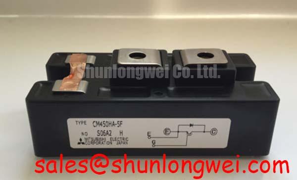
Isolate the power stage, verify that stored energy has been discharged, and disconnect the gate driver before checking the CM450HA-5F with a digital multimeter. Record the terminal markings and existing busbar connections before removing the Mitsubishi Electric IGBT module; a useful cold-test record starts with an electrically isolated device, not readings taken through the surrounding converter circuitry.
Rating verification required: Confirm the electrical ratings and their specified conditions against the manufacturer’s documentation for the exact part before approving procurement or energization.
Measure the isolated main-terminal paths in both polarities using diode-check mode, identifying collector, emitter, and gate from the manufacturer’s terminal drawing rather than their physical position. As an Engineering Recommendation, record the meter model, polarity, and observed response so that a comparison with a known-good module uses the same test conditions. Where the documented circuit includes an antiparallel diode, compare its directional response separately from the transistor path.
A persistent low-resistance reading across the main terminals warrants further investigation, but an in-circuit reading can also include snubbers, discharge resistors, and parallel switching devices. Disconnect those paths before attributing the result to the module. A diode-check indication is a screening observation, not a manufacturer-defined forward-voltage acceptance limit, because the meter’s test current and the device temperature affect the result.
Check gate-to-emitter behavior with the driver disconnected and the gate handled under appropriate electrostatic precautions. Unexpected conduction can justify removing the device from service pending controlled evaluation. Conversely, an apparently open gate does not prove dielectric integrity under switching stress. As a Design Consideration, distinguish this cold screening from a qualified leakage test; do not apply an insulation tester across the gate dielectric unless an approved device-specific procedure explicitly permits it.
Move to waveform capture only after the cold checks and rating verification are complete. Use appropriately rated differential measurement equipment and short probe connections to distinguish actual gate excursions from measurement-loop pickup. During controlled switching tests, compare gate-emitter voltage, collector-emitter voltage, and current on the same time base. Ringing that changes substantially with probe placement deserves a measurement review before gate-drive modifications.
Field Alert: Verify discharge at the actual power terminals before disconnecting gate wiring or loosening busbar connections.
CM450HA-5F Circuit Protection & Reliability: Retrofit Evaluation and Turn-On/Turn-Off Tuning
Compare the existing driver’s source and sink paths before changing turn-on or turn-off resistance. As a Design Consideration, separate gate resistors can allow independent adjustment of switching transitions, but their values depend on the driver output stage, module switching characteristics, busbar inductance, and protection timing. Preserve the original settings as a documented baseline rather than assuming that a faster transition is an improvement.
When evaluating a retrofit, observe the tradeoff between switching loss and transient stress under controlled load conditions. Reduced gate resistance can increase transition speed while aggravating current ringing or voltage overshoot. Increased resistance can soften a transition but extend the interval in which voltage and current overlap. The system engineer should determine acceptable settings from measured waveforms and thermal behavior across the intended operating envelope.
For cross-model evaluation, the CM1200HA-34H is a separate Mitsubishi module to assess against its own documentation, not an asserted replacement for the CM450HA-5F. Compare electrical ratings, circuit configuration, terminal locations, mounting geometry, switching behavior, and driver compatibility before considering any substitution. A shared manufacturer or module category does not establish interchangeability.
Audit semiconductor-fuse coordination using the fuse manufacturer’s clearing characteristics, prospective fault current, and the converter’s protection response. As an Engineering Recommendation, compare clearing energy only with a relevant documented device withstand criterion under compatible conditions. A diode surge rating is not automatically an IGBT short-circuit survival rating, and a fuse does not replace timely gate-drive fault shutdown.
Treat MOVs and local switching-transient suppression as different parts of the protection network. As a Design Consideration, an MOV can absorb suitable incoming or bus-related overvoltage events, while fast local overshoot also depends on commutation-loop layout and the suppression circuit’s placement. Evaluate clamping behavior, absorbed energy, and coordination with other protection elements at system level. The discussion of Resonant Topologies in Home Appliances provides supplementary topology context, not CM450HA-5F ratings or evidence of application suitability.
Transient Dynamics & Electrical Design: Main Power Terminal Contact Resistance on CM450HA-5F
Measure each accessible bolted power connection with a four-wire micro-ohmmeter, placing the voltage-sense contacts across the joint rather than along an uncontrolled length of busbar. As an Engineering Recommendation, keep probe locations consistent and document temperature, joint condition, and instrument setup. Do not impose a universal micro-ohm pass limit: acceptance belongs to the equipment’s qualified connection specification and measurement method.
Inspect mating surfaces, washers, bolt engagement, and busbar alignment before tightening. A busbar that pulls a terminal sideways can compromise the assembly even when the fastener appears secure. Follow the applicable module and equipment assembly instructions for tightening torque and hardware; generic bolt guidance is not a substitute for the allowable mechanical loading of the terminal.
Use thermographic inspection after controlled recommissioning to compare equivalent joints carrying comparable current. As a Design Consideration, a localized temperature rise can support investigation of contact resistance, but emissivity, airflow, adjacent heat sources, and unequal loading can alter the image. Correlate the thermal pattern with electrical measurements rather than assigning a single cause from a hot spot alone.
Route the gate-drive return according to the documented terminal arrangement. If the module drawing explicitly identifies an auxiliary emitter connection, the driver return can be evaluated separately from the main current path; do not infer an auxiliary terminal from appearance. Minimizing shared power-path impedance helps limit gate-reference disturbance, while short, closely coupled gate connections reduce susceptibility to pickup.
Review creepage and clearance wherever changed busbars, mounting hardware, or driver wiring approach another potential. As a Design Consideration, required spacing depends on working voltage, insulation coordination, contamination conditions, and the applicable equipment standard. Gate screening and negative turn-off bias, where supported by the documented device and driver limits, should be assessed against measured common-mode disturbance rather than added as an automatic retrofit measure.
Field Diagnostics & Commissioning: Four-Quadrant Power Flow in Potential CM450HA-5F Applications
Verify commanded power direction against measured DC current and AC power before releasing a repaired converter into bidirectional operation. For a potential utility-scale centralized battery energy storage PCS application, evaluating the CM450HA-5F requires confirmed device ratings and an equipment-level compatibility review. Four-quadrant behavior belongs to the complete converter and its controls, not to an individual IGBT module.
As an Engineering Recommendation, investigate charging and discharging separately during staged commissioning. Confirm current-sensor polarity, switching-state interpretation, and protection response before increasing load. A reversal error can arise from sensing, control configuration, or wiring; waveform capture and controller records help distinguish these possibilities without treating a fault message as a definitive component diagnosis.
Evaluate thermal behavior during transitions between operating states as well as during sustained loading. As a Design Consideration, peak-shaving duty can introduce repeated load changes that alter losses and cooling demand. Record operating current, switching conditions, coolant or heatsink temperature, and protective events together. Those observations support an equipment assessment but do not establish module lifetime or a numerical failure rate.
The reference on Lithium Iron Phosphate (LiFePO4) Battery Storage Chemistries explains battery chemistry context; semiconductor voltage limits and converter protection settings must come from their respective technical documentation. Before releasing the repaired power stage, retain the resolved rating record, terminal measurements, gate waveforms, protection-test results, and assembly checks with the service report.