Content last revised on January 27, 2026
Mitsubishi CM75DY-34A IGBT Module: Engineering High-Voltage Reliability for Industrial Drives
An In-Depth Product Analysis for OEM Engineers and Procurement Specialists
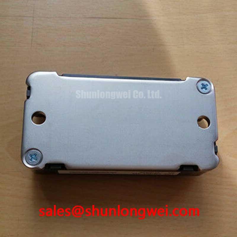
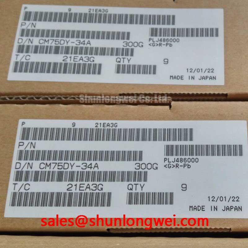
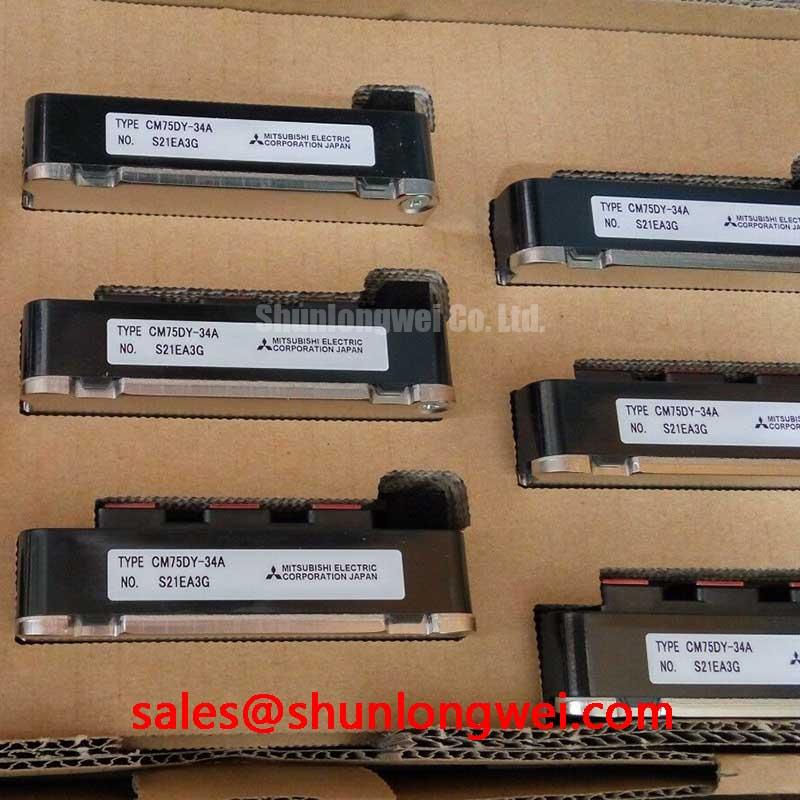
The Mitsubishi CM75DY-34A is a dual IGBT module delivering robust 1700V blocking capability, engineered for high-reliability power conversion in demanding industrial applications. With its specifications of 1700V | 75A | VCE(sat) 2.7V (typ), this A-Series module provides exceptional voltage headroom and a balanced loss profile. Key engineering benefits include enhanced system survivability against voltage transients and simplified thermal design. It directly addresses the need for a durable power switch in systems operating from 690V AC lines, where voltage stability cannot always be guaranteed. For medium-power 690V industrial drives requiring high reliability, the CM75DY-34A's 1700V rating offers the optimal design margin.
Application Scenarios & Value
System-Level Benefits in High-Voltage Motor Control
The primary value of the CM75DY-34A is realized in three-phase power conversion systems, particularly in Variable Frequency Drives (VFDs) and servo drives connected to 690V AC industrial lines. In such environments, the DC bus voltage can approach 1000V, leaving little margin for the voltage overshoots and ringing caused by parasitic inductance during high-speed switching. A standard 1200V module would operate too close to its breakdown limit, compromising long-term reliability.
What is the key benefit of a 1700V rating? It provides a crucial safety margin for systems on unstable 690V AC lines. This module's 1700V VCES rating provides the necessary design headroom to absorb these transient voltages, significantly reducing the risk of catastrophic failure. This allows engineers to design more robust and reliable VFDs for heavy-duty applications like industrial conveyors, pumps, and mixers, where equipment uptime is critical. The integrated dual-switch (half-bridge) configuration, complete with a matched free-wheeling diode, simplifies the layout of each inverter leg, reducing component count and potential points of failure. The module's architecture enables precise control over motor speed and torque through carefully managed Pulse Width Modulation (PWM) schemes.
While the CM75DY-34A is well-suited for 75A applications, for systems demanding higher power throughput with the same voltage margin, the related CM300DY-34A provides a similar 1700V rating with a significantly higher current handling capability.
Key Parameter Overview
Highlighting Critical Specifications for Design Evaluation
The following parameters are extracted from the official datasheet and represent the core electrical and thermal characteristics crucial for system modeling and performance evaluation. The values highlighted in bold are pivotal for loss calculations and reliability assessments.
| Absolute Maximum Ratings (Tj = 25°C unless otherwise noted) | |
|---|---|
| Collector-Emitter Voltage (VCES) | 1700V |
| Gate-Emitter Voltage (VGES) | ±20V |
| Collector Current (IC) | 75A |
| Collector Power Dissipation (Pc) | 520W |
| Junction Temperature (Tj) | -40 to +150°C |
| Electrical Characteristics (Tj = 25°C) | |
| Collector-Emitter Saturation Voltage (VCE(sat)) at Ic=75A | 2.7V (Typ.), 3.4V (Max) |
| Gate-Emitter Threshold Voltage (VGE(th)) | 5.5V (Typ.) |
| Turn-On Switching Energy (Eon) per pulse | 17 mJ (Typ.) |
| Turn-Off Switching Energy (Eoff) per pulse | 22 mJ (Typ.) |
| Reverse Recovery Time (trr) of FWD | 0.25 µs (Typ.) |
| Thermal Characteristics | |
| Thermal Resistance, Junction to Case (Rth(j-c)) per IGBT | 0.24 °C/W |
| Thermal Resistance, Junction to Case (Rth(j-c)) per Diode | 0.45 °C/W |
Download the CM75DY-34A datasheet for detailed specifications and performance curves.
Technical Deep Dive
Analyzing the VCE(sat) vs. Switching Loss Trade-Off
The performance of any IGBT is defined by the inherent trade-off between conduction losses (governed by VCE(sat)) and switching losses (determined by turn-on/off times and energies). For the CM75DY-34A, the typical VCE(sat) of 2.7V at its nominal current is a deliberate design choice for a 1700V device. A higher blocking voltage capability generally requires a thicker drift region in the silicon die, which naturally increases on-state resistance and thus VCE(sat).
This balance is critical for application-specific efficiency. Think of it like a water valve: a very low VCE(sat) is like a massive, wide-open pipe that offers little resistance to flow (low conduction loss). However, such a massive valve would be heavy and slow to close, causing a lot of turbulence and splashing (high switching loss) each time it operates. The CM75DY-34A is engineered to be a more agile valve—while the pipe isn't quite as wide, its ability to open and close quickly minimizes the "splashing," making it highly efficient in systems that require frequent switching. This makes it a versatile component, performing reliably in applications with moderate PWM frequencies (e.g., 5-15 kHz) where both conduction and switching losses are significant contributors to the overall thermal load.
Frequently Asked Questions (FAQ)
How does the 1700V VCES rating impact the gate drive design compared to a 1200V module?
While the fundamental gate drive requirements are similar (e.g., providing sufficient gate charge), the higher voltage rating necessitates more attention to layout practices that minimize parasitic inductance. The faster voltage transitions (dv/dt) across a 1700V device can induce larger voltage spikes. A clean layout, proper gate resistor selection, and potentially a snubber circuit become more critical to prevent gate-emitter overvoltage and ensure reliable switching.
What is the primary implication of the 0.24 °C/W thermal resistance (Rth(j-c))?
This value quantifies how efficiently heat can be transferred from the IGBT junction to the module's case. A lower number is better. This specific value allows engineers to accurately calculate the junction temperature under a given power loss scenario, which is the cornerstone of reliable thermal management. It is a direct input for selecting an appropriately sized heatsink to keep the junction temperature well below the 150°C maximum limit, ensuring the module's longevity.
Is this module suitable for applications with high short-circuit current risks?
The datasheet for the A-Series, including the CM75DY-34A, typically specifies short-circuit withstand capabilities. However, system-level protection is paramount. The module's survival depends on a fast-acting gate drive circuit that can detect the desaturation condition and safely turn off the IGBT within the specified short-circuit withstand time (typically in the range of microseconds). For a detailed guide, see our article on preventing IGBT failures.
Can the CM75DY-34A be used in parallel to increase current capacity?
While paralleling IGBT modules is a common practice, it requires careful design to ensure proper current sharing. Key parameters like VCE(sat) and VGE(th) have negative temperature coefficients, which can lead to thermal runaway in one module if not managed. Successful paralleling involves matching device characteristics, using individual gate resistors, and employing a symmetrical layout to balance stray inductances. It's an advanced technique that requires thorough analysis.
Strategic Fit & Long-Term Value
A Building Block for Resilient Power Systems
Selecting the CM75DY-34A is a strategic decision that prioritizes system robustness and operational reliability over chasing the absolute lowest conduction loss figure. In the landscape of industrial automation and renewable energy, where equipment operates in electrically noisy and often unpredictable environments, designing with an adequate safety margin is a key tenet of long-term value. This module from Mitsubishi Electric provides a proven, reliable foundation for power electronics engineers tasked with building high-performance systems that are, above all, built to last.

