Content last revised on January 24, 2026
VUB145-16NOXT: Engineering High-Efficiency Power Conversion
A Technical Introduction to the 1600V, 145A Three-Phase Rectifier
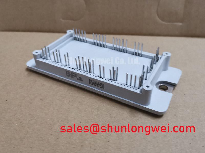
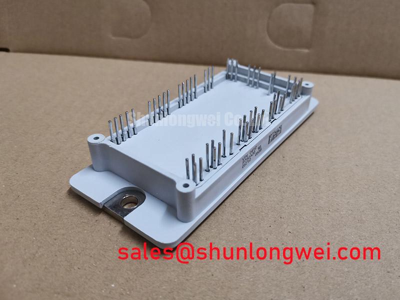
The VUB145-16NOXT is a high-efficiency 1600V three-phase bridge rectifier engineered for superior thermal performance and long-term reliability in demanding industrial power stages. This module integrates six planar passivated diodes in a robust, isolated package, delivering key specifications of 1600V, 145A, and a low maximum forward voltage drop of 1.29V. Its design priorities are clear: reduced thermal load and enhanced system survivability. It directly addresses the engineering challenge of creating compact and efficient input stages for 400V/480V AC line systems by minimizing conduction losses and simplifying thermal management. For industrial drives and high-power SMPS requiring a robust front-end, the VUB145-16NOXT is the optimal choice for thermal efficiency.
Application Scenarios & Value
Optimizing the Input Rectifier Stage in Industrial Drives and Power Supplies
The primary application for the VUB145-16NOXT is the input rectifier stage of high-power systems such as Variable Frequency Drives (VFDs), switched-mode power supplies (SMPS), and battery chargers. In these applications, a key engineering challenge is managing the heat generated by the front-end rectifier, especially within compact or sealed enclosures. The module's low forward voltage drop (VF) is a decisive factor here. Lower VF directly translates to lower conduction losses (P = VF x I), meaning less energy is wasted as heat.
Consider a VFD operating under a heavy load. The VUB145-16NOXT's ability to efficiently convert the incoming AC power to a stable DC bus voltage with minimal heat generation allows designers to specify smaller, more cost-effective heatsinks or operate the system at higher ambient temperatures without derating. What is the primary benefit of its DCB substrate design? Enhanced thermal transfer and high electrical isolation. This thermal efficiency is critical for improving overall system power density and reliability. For systems requiring lower current handling, the related VUB72-16NO1 provides a similar voltage rating in a 72A package.
Key Parameter Overview
Critical Specifications for Thermal Design and System Reliability
The performance of the VUB145-16NOXT is defined by electrical and thermal parameters that directly influence its suitability for high-stress industrial environments. The following table highlights the specifications most critical for design engineers focused on efficiency and longevity.
| Parameter | Symbol | Condition | Value |
|---|---|---|---|
| Repetitive Peak Reverse Voltage | V_RRM | 1600 V | |
| Average Forward Current | I_DAV | T_C = 80°C, per diode | 145 A |
| Peak Forward Surge Current | I_FSM | t = 10 ms, T_VJ = 45°C | 1800 A |
| Forward Voltage Drop (max) | V_F | I_F = 150 A, T_VJ = 25°C | 1.29 V |
| Thermal Resistance, Junction to Case | R_th(j-c) | Per diode | 0.44 K/W |
| Isolation Voltage | V_ISOL | 50/60 Hz, RMS, t = 1 min | 3600 V~ |
| Operating Junction Temperature | T_VJ | -40 to +150 °C |
Download the VUB145-16NOXT datasheet for detailed specifications and performance curves.
Technical Deep Dive
A Closer Look at the DCB Substrate and its Impact on Thermal Cycling Reliability
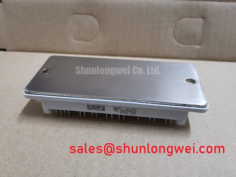
A key feature contributing to the VUB145-16NOXT's robustness is its use of a Direct Copper Bonded (DCB) aluminum oxide (Al2O3) substrate. This construction, where a ceramic insulating layer is directly bonded between two layers of copper, offers significant advantages over older technologies. The most critical benefit relates to reliability under thermal cycling. Power modules are constantly heating and cooling as load conditions change. The silicon diode chips and the copper baseplate expand and contract at different rates, creating mechanical stress on the solder joints that connect them.
The DCB substrate acts as an engineered intermediary. Its coefficient of thermal expansion (CTE) is much closer to that of the silicon itself. This is like building a bridge with materials that all react to temperature changes in a similar way, preventing buckling and cracking. By minimizing the CTE mismatch, the DCB construction dramatically reduces the strain on the solder joints, leading to a much longer service life and higher resilience against failures caused by metal fatigue. This foundational design choice is a primary reason for the module's "improved temperature and power cycling" capability, a critical factor in applications with frequent start/stop cycles or fluctuating loads. For a deeper understanding of these concepts, explore resources on unlocking IGBT thermal performance.
Frequently Asked Questions
Engineering Questions on the VUB145-16NOXT
How does the low forward voltage drop (VF) of the VUB145-16NOXT benefit the overall system design?
A lower VF directly reduces power loss during conduction (Power Loss = VF x Current). This results in less heat being generated, which allows for the use of smaller, lighter, and more cost-effective heatsinks. It also improves overall system energy efficiency and can increase the power density of the final product.
What is the significance of the 1800A surge current rating (IFSM) in practical applications?
The high surge current rating indicates the module's ability to withstand large, brief inrush currents without failing. This is crucial during system startup when charging large DC bus capacitors or during fault conditions on the AC line. This robustness enhances system survivability and prevents catastrophic failure of the input stage.
What advantages does the Direct Copper Bonded (DCB) substrate offer over other isolation technologies?
The primary advantages are superior thermal conductivity and enhanced reliability. DCB provides a very efficient path for heat to move from the silicon dies to the heatsink while ensuring high electrical isolation (3600V~). Its thermal expansion characteristics are well-matched to silicon, reducing mechanical stress during temperature cycles and significantly improving the module's long-term operational life.
Is the VUB145-16NOXT suitable for rectifying a 480V AC three-phase line?
Yes. A 480V RMS AC line has a peak voltage of approximately 679V (480V * sqrt(2)). The VUB145-16NOXT's 1600V repetitive peak reverse voltage (VRRM) rating provides a substantial safety margin, making it a very reliable choice for 400V, 480V, and even 575V nominal AC line applications, ensuring safe operation even with line transients.


