
Content last revised on October 28, 2026
Preventing Spurious Faults: DC-DC Converter Interleaving and Ripple Current Guidelines for CM800DW-34T
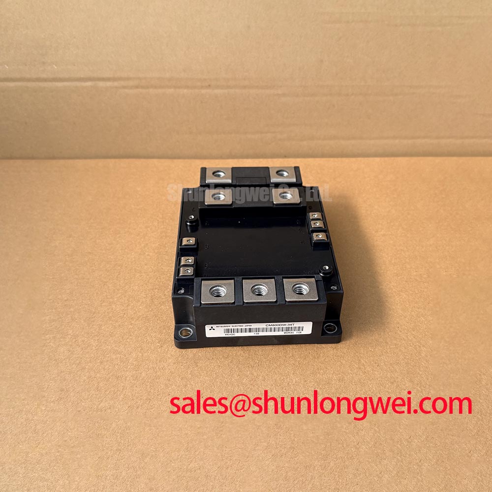
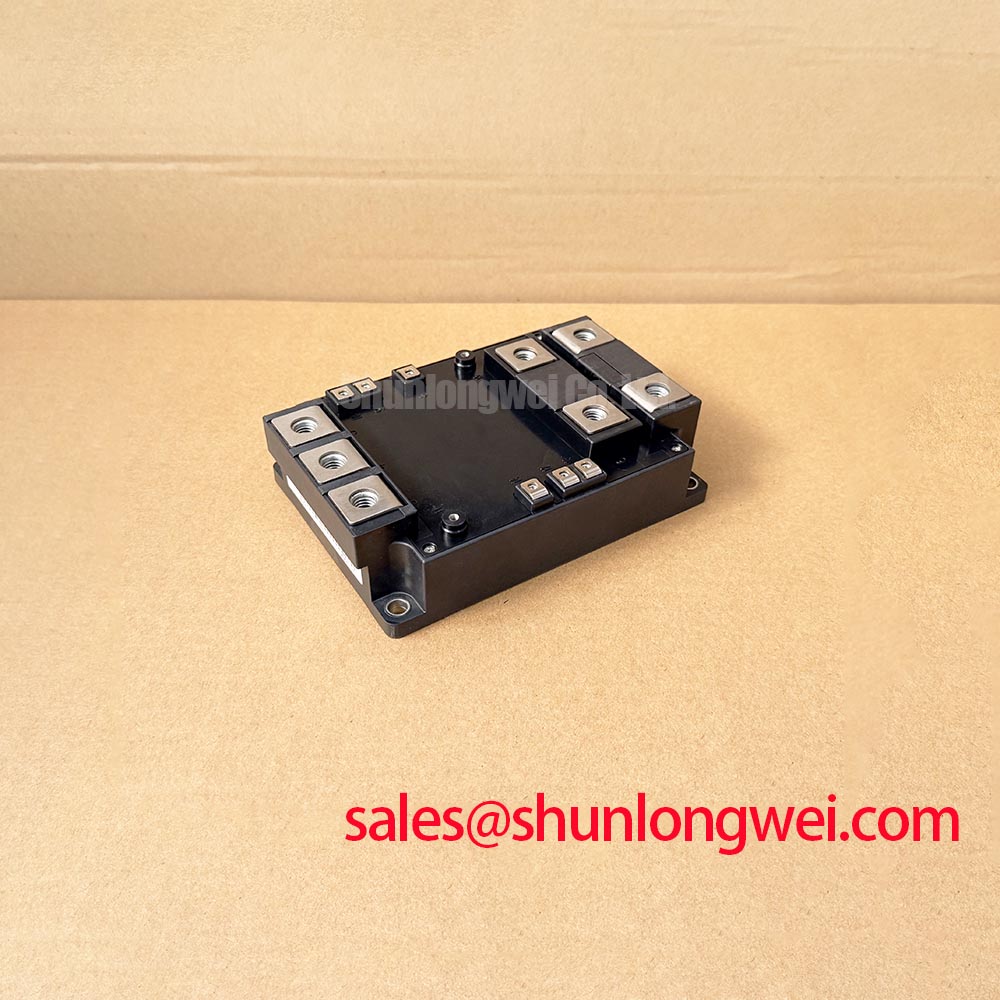
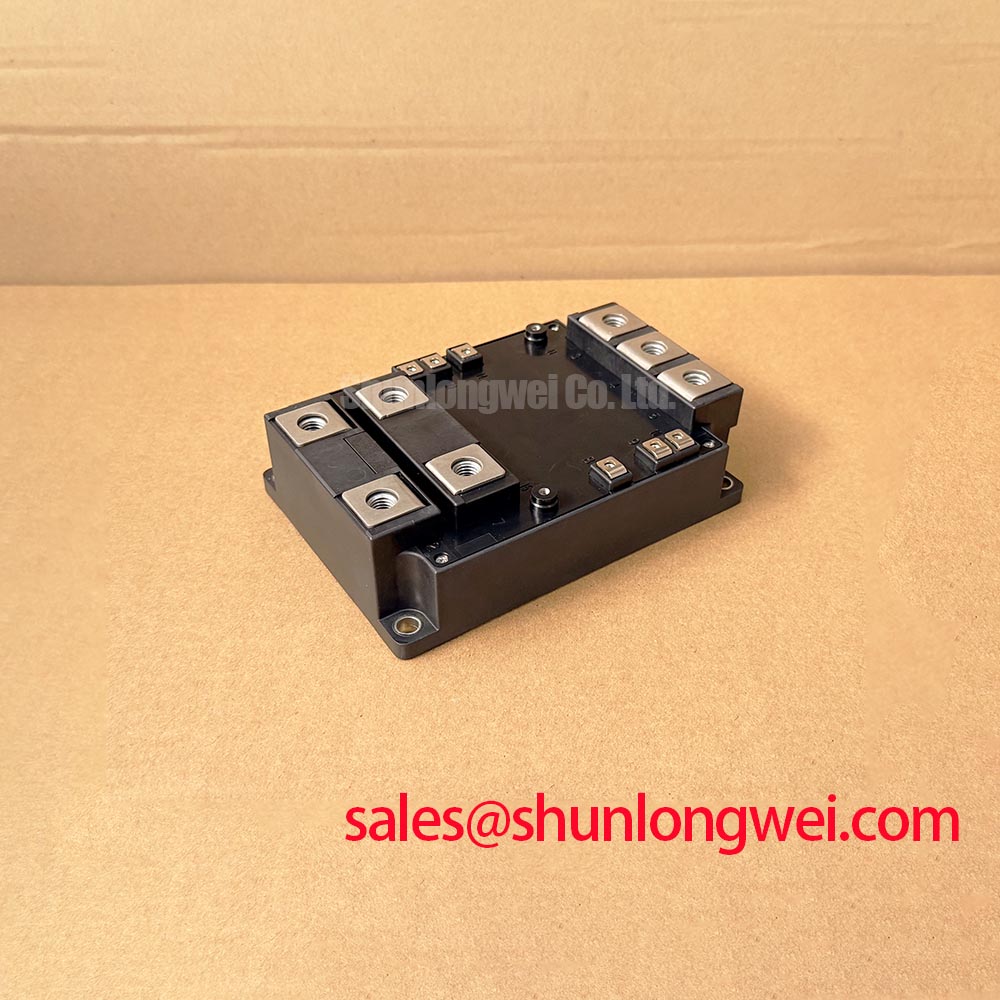
I compare the fault timestamp with DC-link ripple, phase-current balance, and the commanded power reversal before treating a converter trip as a failed CM800DW-34T. Its 1700 V voltage rating and 800 A current rating are Official Specifications, not operating setpoints. The operating envelope must account for switching overshoot, cooling conditions, and the electrical limits associated with the actual duty cycle.
Design Consideration: When evaluating this module for a utility-scale centralized battery energy storage PCS, distinguish bidirectional battery power transfer from grid-side four-quadrant operation. The battery-side converter manages charging and discharging, while the inverter controls active and reactive grid current. A disturbance during power reversal can originate in current-loop coordination, DC-link regulation, or protection timing rather than the power module itself.
For an interleaved DC-DC stage, compare phase-current waveforms under the same load condition. Unequal phase loading can concentrate conduction losses even when aggregate battery current appears acceptable. Inspect phase synchronization, current-sensor offsets, magnetic-component behavior, and copper-path symmetry. Ripple cancellation depends on the operating point and phase relationship; it does not eliminate local high-frequency current in module terminals and DC-link connections.
Keep commutation paths compact while preserving the required electrical clearance between conductors. Copper width alone does not establish acceptable ripple-current heating: joints, overlap geometry, cooling, and proximity effects also influence temperature. During repeated high-power transitions, correlate case-temperature trends with phase imbalance rather than attributing every thermal swing to battery C-rate.
Battery chemistry and charge estimation provide operating context, not semiconductor ratings. The references on lithium iron phosphate battery chemistry and state of charge explain why battery conditions vary across a charge cycle; neither establishes a permissible module switching condition. If a system review also includes CM150RX1-24A, evaluate its documented circuit function separately rather than assuming it is an interchangeable rectifier or companion power stage.
CM800DW-34T Thermal-Electrical Optimization: Unpowered Bench Screening with a Multimeter
Discharge the DC link, verify the absence of hazardous voltage, and isolate parallel circuit paths before using diode-check mode across the module’s documented main terminals. An installed snubber, discharge network, or neighboring switch can alter the reading and obscure which path the meter is measuring.
Design Consideration: Identify collector, emitter, and gate connections from the module terminal drawing before probing. For each documented antiparallel diode path, record the meter polarity and compare forward and reverse behavior with an equivalent known-good path under matching conditions. A diode-check reading is a low-energy screening observation; it does not demonstrate rated-current conduction, reverse-blocking capability, or switching performance.
Check for gross gate-to-emitter and gate-to-collector shorts without allowing the gate to float during handling. A multimeter resistance measurement can reveal an obvious abnormality, but it is not a quantitative gate-leakage qualification. Proper leakage assessment requires a controlled test setup using the manufacturer’s specified conditions. Record instrument mode and connection orientation so that later comparisons remain meaningful.
Before returning the assembly to powered testing, inspect complementary gate interlocks and the driver return paths. Dead time should accommodate actual turn-off behavior, propagation mismatch, and temperature dependence without unnecessarily extending diode conduction. Establish it from the driver and switching-stage measurements rather than from a generic timing value. Observe the gate waveform at the device connection with an appropriate measurement arrangement, not only at the controller output.
Miller-induced gate movement and common-mode ground bounce deserve separate attention. Short gate-return loops, separation from power-current paths, and correctly referenced shielding can reduce unwanted coupling. Any negative turn-off bias or active clamping arrangement must remain within the device and driver limits.
For maintenance sourcing, compare CM800HA-28H only as a separate candidate requiring a complete electrical and mechanical review, not as an approved substitute. Match voltage capability, circuit configuration, terminal mapping, driver requirements, and mounting geometry before considering a replacement.
CM800DW-34T Circuit Protection & Reliability: Assessing Pollution Degree 3 Creepage Distances
Inspect the terminal-to-baseplate insulation path for contamination, moisture tracks, damaged barriers, and displaced hardware before selecting an insulation-test procedure. External surface condition and internal dielectric condition are different questions; a clean housing alone cannot establish insulation integrity.
Design Consideration: Pollution degree is an equipment-environment classification, not a property established by the CM800DW-34T part number. IEC 60664-1 provides an insulation-coordination framework for applicable equipment. Creepage assessment considers working voltage, pollution conditions, and insulating-material characteristics; clearance assessment also considers the relevant impulse withstand requirement and installation conditions. Measure the shortest actual paths around terminals, busbars, fasteners, and nearby grounded metal.
Do not adopt an arbitrary insulation-resistance acceptance threshold or test voltage as a manufacturer requirement. Use the applicable module test instructions and equipment service procedure, including terminal grouping, test duration, disconnected circuitry, and discharge precautions. A high-voltage test applied through attached drivers or sensing circuits can stress components outside the intended insulation boundary. Terminal-to-baseplate resistance testing also does not identify a particular internal substrate material or prove its structural integrity.
For industrial airborne dust, inspect deposits at terminal edges and beneath protective covers. Cleaning and barrier restoration should follow material-compatible service procedures. Where the cabinet environment can create conductive contamination, enclosure control and insulation coordination must be addressed together rather than compensating with an assumed universal spacing.
Coordinate MOV-based surge protection with the wider DC-link protection network. MOV clamping behavior depends on pulse current, tolerance, temperature, and accumulated stress; it should not be treated as a substitute for controlling local commutation inductance. Distinguish incoming-system surge protection from the fast overshoot occurring at the switching terminals.
The Wide Bandgap Revolution technical overview offers context on switching-related layout challenges. Its discussion of GaN and SiC should not be transferred into claims about this IGBT module’s materials, insulation construction, or reliability qualification.
Assembly Integrity & Layout Architecture: Applying Transient Thermal Impedance for CM800DW-34T
Reconstruct the overload pulse history before estimating junction temperature: record conduction intervals, switching events, case temperature, and the cooling boundary during the event. Average cabinet power can conceal a short junction-temperature peak, particularly when successive pulses arrive before the thermal system has recovered.
Engineering Calculation: For a constant-loss pulse under the boundary conditions of the applicable thermal model, the junction-temperature rise can be estimated as ΔTj = P × Zth(j-c)(t). Here, P is device loss and Zth(j-c)(t) is the corresponding junction-to-case transient thermal impedance. For repeated or changing pulses, superpose the incremental thermal responses or use a validated multi-RC model driven by the loss waveform. Use model parameters fitted to the relevant manufacturer curve, not coefficients borrowed from another module.
Add the calculated temperature rise to the case-temperature boundary used by the model, then compare the resulting peak with the documented junction-temperature limit. Keep model interpretation consistent: an equivalent RC network is not automatically a physical layer-by-layer representation. Switching losses, conduction losses, and any diode losses must be assigned to the appropriate thermal paths.
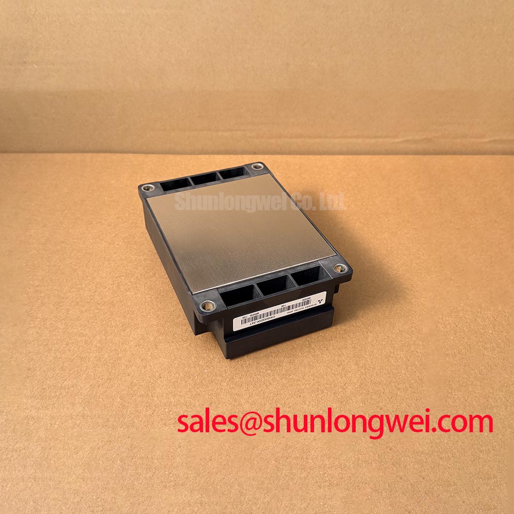
At the mounting interface, inspect heatsink flatness, surface cleanliness, thermal-interface coverage, and fastening sequence. Apply the module’s specified assembly procedure rather than transferring torque or interface-thickness values from another package. Flat-press clamping, disc-spring preload calibration, and double-sided cooling are architecture-specific methods; none should be assumed to describe this module merely because its package category is “Module.”
Pro Tip: Use symmetric, closely coupled busbar paths to reduce turn-off overshoot, then verify the resulting voltage margin with a double-pulse test at representative operating conditions.
During that test, separate fixture-induced ringing from device-terminal behavior through suitable probing and repeatable connections. Correlate the measured switching waveforms with the loss inputs used in the thermal model. If calculated and measured temperature trends diverge, investigate interface contact, case-sensor placement, cooling stability, and loss assumptions before adjusting the permitted overload profile.