

Content last revised on October 9, 2026
Field Diagnostics & Commissioning: Baseplate Thermal Grease Layer Control in CM800E3UA-24F Topologies
| Product model | CM800E3UA-24F |
|---|---|
| Manufacturer | Mitsubishi Electric |
| Product category and package | IGBT Module; module package |
| Rated voltage | 1200 V — Official Specification |
| Rated current | 800 A — Official Specification |
Inspect the removed module’s thermal compound imprint and heatsink contact surface after isolating the equipment and verifying that the DC link is discharged. Uneven transfer, isolated dry patches, displaced compound, and contamination justify checking the mounting interface rather than immediately attributing overheating to semiconductor damage. Record the imprint before cleaning: it can help distinguish incomplete seating from an uneven heatsink surface.
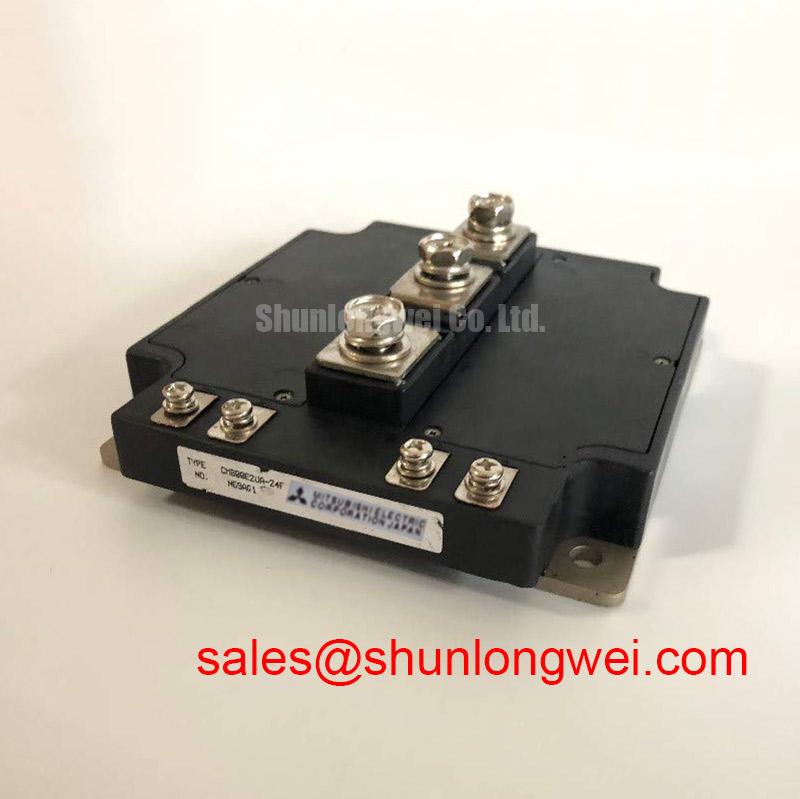
CM800E3UA-24F is a Mitsubishi Electric 1200 V, 800 A IGBT module. These official ratings establish its electrical class; they do not specify an allowable operating point for every cooling arrangement. As a Design Consideration, the equipment’s continuous loading must account for switching losses, conduction losses, coolant conditions, and the complete thermal path. A nameplate current alone cannot establish the permissible converter output.
Design Consideration: inspect heatsink flatness, mounting-hole condition, and baseplate seating against the applicable mechanical drawing. Do not attempt to straighten the baseplate or fill a substantial mechanical gap with extra grease. Controlled compound application should wet the mating surfaces without leaving trapped voids or unnecessary thermal resistance. Determine the application thickness from the approved interface material and assembly procedure, not a generic thickness range presented as a module specification.
Seat the module without loading its electrical terminals, then tighten mounting fasteners progressively in the sequence specified for the assembly. Use the documented torque for the actual fastener and mounting arrangement; mounting screws and power-terminal screws need not share a torque requirement. Preserve clearance around terminals and avoid forcing misaligned busbars into position.
Field Alert: Never use the terminal bolts to pull a misaligned busbar into place; correct the mechanical alignment before tightening.
For cold electrical screening, disconnect paths that would obscure measurements and compare collector–emitter and gate–emitter readings with an equivalent, known-good circuit under the same meter polarity. Capacitors, gate resistors, and connected driver circuitry can influence readings. A multimeter can reveal gross anomalies, but it cannot verify high-voltage blocking capability or switching performance. Keep measurement results separate from a final serviceability decision.
Benchtop Waveform Tuning: Mitigating Stress and Assessing FIT Requirements for CM800E3UA-24F
Capture collector–emitter voltage during turn-off and compare the peak waveform with the DC-link voltage at the same operating condition. Use appropriately rated differential measurement equipment and a controlled commissioning procedure. Check probe placement and bandwidth before interpreting ringing; measurement-loop pickup can make the apparent stress substantially different from the voltage at the module terminals.
Design Consideration: minimize commutation-loop inductance to reduce turn-off overshoot, then validate the assembled converter across its intended load and temperature range. The module’s 1200 V rating is not a recommended DC-bus setting. Bus voltage, transient suppression, gate-drive behavior, and protection response together determine the operating margin. No fixed voltage headroom percentage follows from the supplied ratings.
If the equipment includes a regenerative braking chopper, compare DC-link rise with the chopper command, resistor current, and protection records. Verify resistor continuity and its thermal protection independently. A rising bus can involve regeneration, unavailable energy absorption, a control fault, or an interrupted power path. Do not assign the CM800E3UA-24F to that circuit position without checking the equipment schematic and module connection drawing.
Design Consideration: investigate cooling repeatability alongside the electrical waveforms. A poorly seated interface can change case temperature and complicate comparisons between switching tests. Keep the compound application method and mounting sequence consistent when comparing assemblies. Neither a chosen grease thickness nor a screw-tightening pattern establishes a failures-in-time rate.
For installations requiring cosmic-ray or single-event burnout assessment, obtain device-specific reliability information and the project’s environmental requirements. The 1200 V, 800 A ratings do not support a numerical FIT calculation, altitude threshold, or lifetime prediction. Any voltage derating for that purpose requires applicable manufacturer data and system-level review; waveform tuning alone cannot quantify that reliability mechanism.
The engineering discussion of Resonant Topologies in Home Appliances offers a separate topology comparison, not qualification evidence for this module. Likewise, Zero-Voltage Switching (ZVS) Resonant Converters explains general switching principles; reduced switching voltage does not establish an application-specific failure rate.
Benchtop Waveform Tuning: Mitigating Stress via Active Miller Clamp Implementation on CM800E3UA-24F
Measure gate–emitter voltage at the module connection while the complementary switching path commutates, and check for an unintended rise during the commanded off state. Reference the measurement to the appropriate emitter connection shown in the module drawing. Comparing only the driver output can miss voltage developed along the gate and return wiring.
Design Consideration: an active Miller clamp provides a low-impedance discharge path when changing collector voltage couples current into the gate circuit. Its effectiveness depends on clamp placement, return-path impedance, driver timing, and the module’s switching behavior. Select and validate the implementation with the actual driver and power-stage layout rather than assuming that adding a clamp automatically prevents cross-conduction.
Reverse-transfer capacitance, commonly designated Cres, is a capacitance characteristic, not Miller plateau charge. Gate-charge behavior and capacitance curves serve different purposes when evaluating driver loading and induced gate movement. Their values and test conditions are not supplied here, so no gate resistance, clamp-current requirement, or negative gate-bias voltage can be assigned as a CM800E3UA-24F specification.
When evaluating negative off-state bias, check the module’s permissible gate voltage and the driver’s output limits. Determine the operating bias through the approved design and switching tests. Also compare the isolator’s common-mode transient immunity with the measured switching environment. An unexpected gate pulse may involve coupling, driver-supply disturbance, isolation behavior, or measurement error; investigate these paths separately.
Design Consideration: diode reverse recovery can influence commutation current, ringing, and emissions. Evaluate the relevant waveforms under matched current and temperature conditions rather than assigning an unsupported recovery softness factor. The 800 A rating also does not establish a diode surge-current limit or a safe recovery interval after overload. Those checks require the applicable device limits and protection records.
Where an auxiliary supply appears in the converter schematic, Buck Converter Step-Down Voltage Regulation provides useful background on supply operation. Keep that analysis distinct from module selection. The CM30TF-12E can be reviewed as another power-module product during a wider topology assessment, but its presence in the same catalog does not establish a complementary circuit role.
Assembly Integrity & Layout Architecture: Implementing Thermal Feedback for CM800E3UA-24F
Compare case-temperature trends, branch-current waveforms, and mounting-interface condition across parallel power paths under matched loading. Use equivalent sensor placement so that a difference in measurement geometry is not mistaken for unequal dissipation. Investigate cooling distribution and electrical connections before attributing a temperature difference to the module itself.
Design Consideration: a positive temperature coefficient of collector–emitter saturation voltage can support static current sharing in an appropriate operating region. That behavior must be established from the device’s characteristic curves at the relevant current and gate voltage; it is not confirmed by the supplied voltage and current ratings. Dynamic sharing also depends on switching timing, gate-loop impedance, and power-path symmetry.
Maintain comparable gate and return routing between parallel branches, and assess conductor arrangement and terminal contact condition. Thermal feedback should reflect the available sensing location and its response delay. A heatsink measurement is not an instantaneous junction-temperature measurement, so protection thresholds and filtering belong to the validated equipment design rather than an assumed module capability.
For replacement assessment, compare the exact CM800E3UA-24F designation with the equipment bill of materials, connection drawing, and mechanical interface. The CM150DU-34KA is a separate candidate for specification comparison, not a verified direct replacement. Electrical topology, ratings, mounting dimensions, terminal positions, and driver compatibility must all support an interchange decision.
When evaluating integration into a multi-megawatt offshore or onshore wind turbine full-scale converter, verify the individual switch position and its loading rather than treating the converter’s total power as a module rating. Retain the approved cooling arrangement and protection coordination, then document branch-current balance, thermal response, and switching peaks during controlled recommissioning.