


Content last revised on October 28, 2026
DD200KB40 Thermal-Electrical Considerations: Sinusoidal Half-Cycle Surge Current Practical Tuning
- Isolate the power assembly, verify that stored energy has discharged, and disconnect parallel paths before checking terminal conduction.
- Match the DD200KB40 terminal diagram to the equipment schematic before reconnecting busbars.
- Inspect the mounting surface, terminal contact faces, and heatsink interface for damage or uneven seating.
- Record the protection fuse designation and cooling arrangement before assessing replacement compatibility.
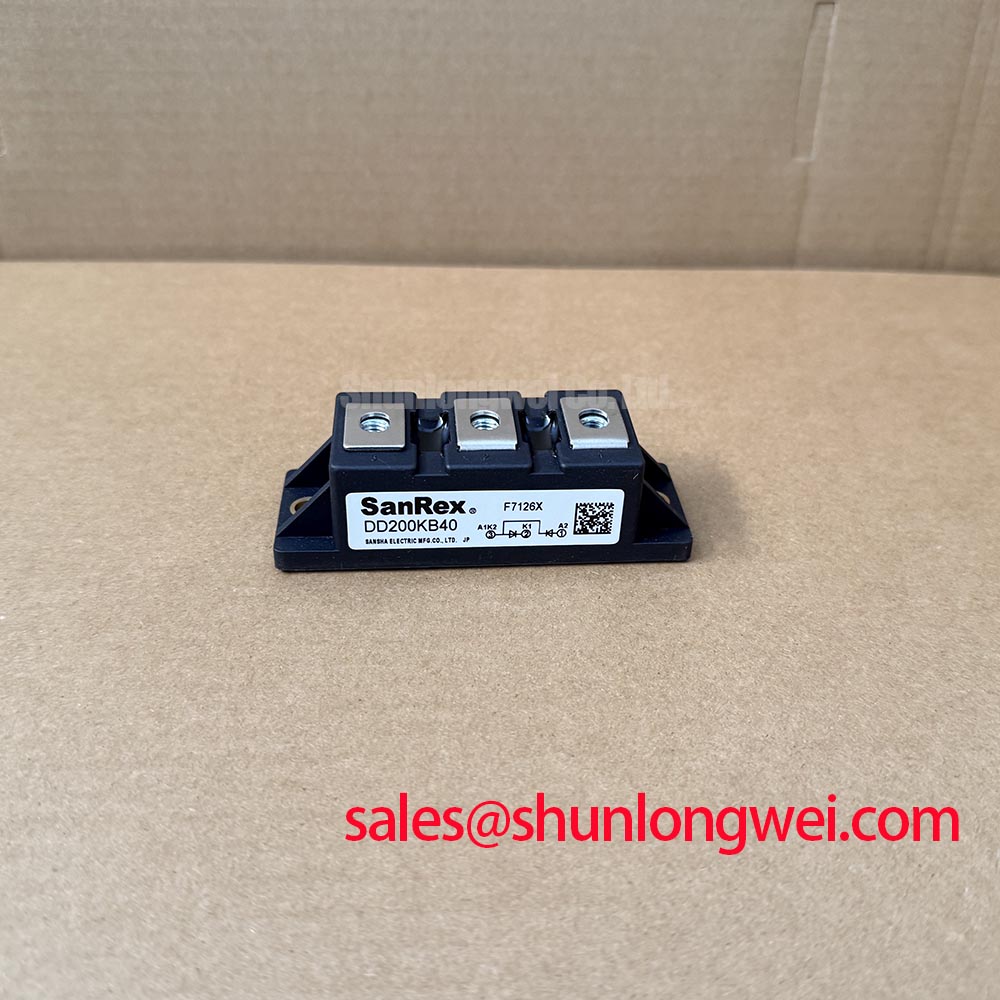
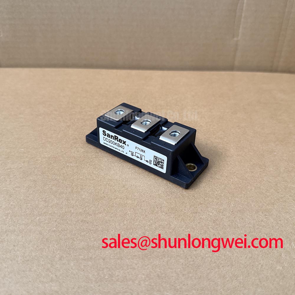
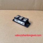
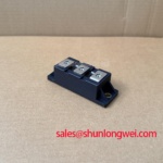
DD200KB40 is identified here as a diode module with a PowerBlock Module package description. A diode conducts according to its terminal bias; it does not accept a gate firing command. That distinction determines which surge, protection, and waveform checks belong in the service procedure.
| Identification item | Product reference |
|---|---|
| Model | DD200KB40 |
| Manufacturer reference | Infineon; manufacturer attribution requires confirmation against the original device documentation |
| Product category | Diode Module |
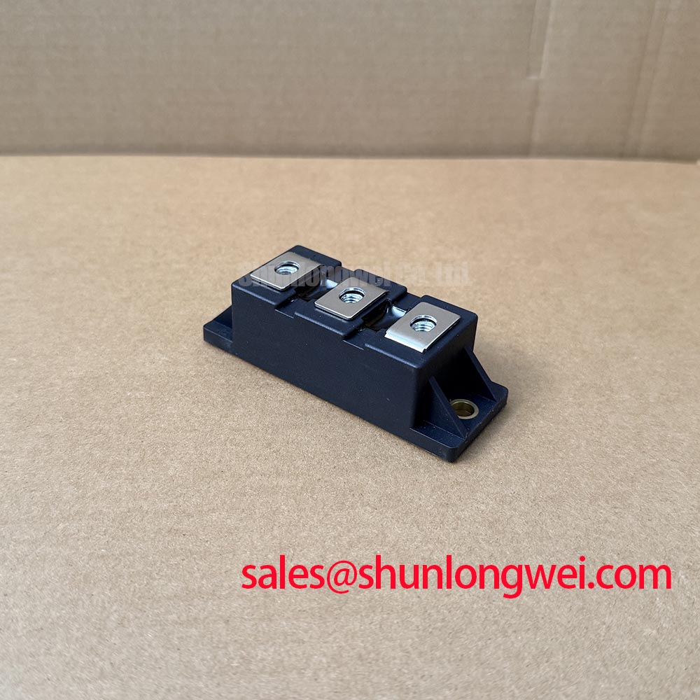
| Package description | PowerBlock Module |
| Electrical and mechanical limits | Consult Datasheet for numerical voltage, current, surge, junction temperature, terminal assignment, dimensions, and tightening torque; the supplied rating descriptions are not numerical specifications |
Match the surge waveform and initial junction temperature to the conditions attached to the manufacturer's surge-current rating before assessing an overload event. Design Consideration: a sinusoidal half-cycle withstand rating describes a particular transient test, not permission for repetitive overload. A 10 ms interval must not be treated as a confirmed DD200KB40 test condition.
Reverse-voltage reapplication matters because a diode emerging from a high-current event can encounter blocking stress while its junction remains hot. Review the overload duration, preceding load, cooling conditions, and subsequent voltage waveform together. A brief current peak alone does not establish whether the complete event remains within the device's operating boundaries.
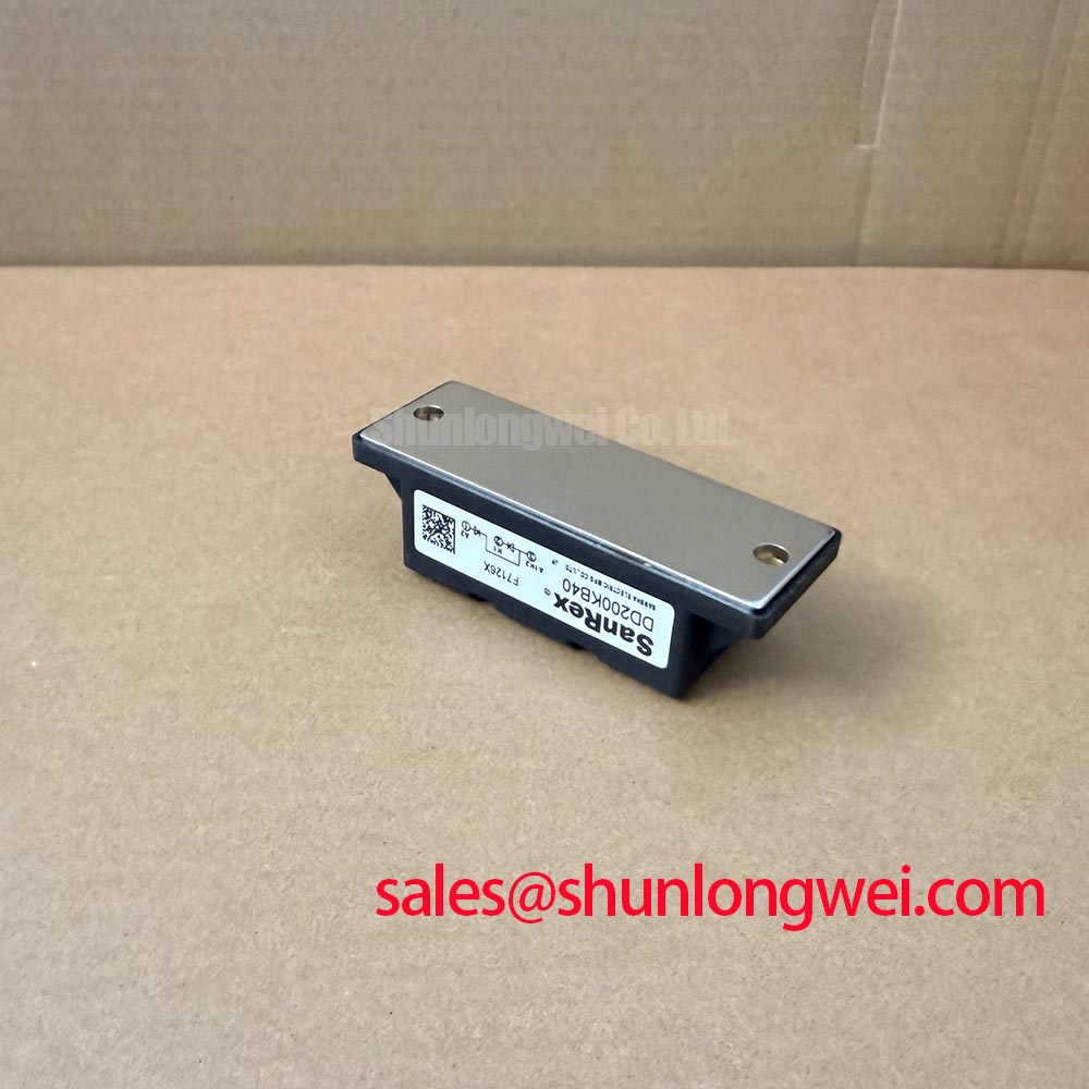
Mechanical assembly belongs in this assessment. Check that the module seats evenly and that busbars do not pull its terminals out of alignment. Use the device-specific fastening instructions rather than transferring a torque value from a visually similar housing. Uneven contact pressure or a disturbed thermal interface can change the operating temperature without an obvious change in load current.
For sourcing comparisons, DD89N18 provides another product reference to examine against the required circuit configuration, blocking capability, thermal limits, and mounting drawing. Its inclusion does not establish interchangeability with DD200KB40.
DD200KB40 Operational Boundaries: Evaluating Semiconductor Protection Fuse Selection in Limits
Compare the fuse's total clearing I²t with the semiconductor's applicable withstand limit under matching fault conditions. Design Consideration: pre-arcing I²t alone excludes the energy passed during arcing, so it cannot represent the complete protection event. Prospective fault current, circuit voltage, and the fuse manufacturer's application conditions also affect coordination.
Build the coordination record around the actual fuse designation, total clearing characteristic, module withstand condition, initial thermal state, and circuit fault level. Use these entries to identify incompatible assumptions before approving the assembly. I²t coordination does not guarantee zero damage during every short circuit; peak let-through current, arc voltage, and connection integrity remain relevant.
Trace the rectifier and associated power branches separately. The DD1200S45KL3_B5 is a separate power-device reference for complementary-stage assessment, not a prescribed companion or replacement. Each branch needs protection appropriate to its own device ratings and fault-current path.
When evaluating a grid-tied static var compensator or thyristor-switched capacitor assembly, distinguish a diode branch from the controlled thyristor branch on the schematic. System-level equipment names do not establish device compatibility or application approval. Likewise, Infineon Automotive Qualified Power Modules concerns a separate product scope and does not establish automotive qualification for DD200KB40.
Benchtop Waveform Tuning: Mitigating Stress via Pulse-Transformer Isolated Firing Circuit on DD200KB40
Trace any pulse-transformer output to the controlled semiconductor rather than assigning a gate connection to DD200KB40. Gate pulse rise time, holding current, and multipulse firing are thyristor-drive considerations; they are not diode-module adjustment parameters. Negative gate bias, Miller suppression, and Kelvin-emitter routing likewise should not be attributed to this diode without an applicable device structure.
For the diode branch, inspect current commutation and terminal-voltage overshoot using appropriately rated measurement equipment. Design Consideration: reverse recovery interacts with circuit inductance and switching conditions, so ringing alone does not establish an intrinsic recovery defect. Compare measurements at equivalent load and temperature, and check probe connections before interpreting high-frequency features.
Practical tip: Minimize the commutation-loop area to reduce inductive overshoot, then validate the resulting terminal-voltage waveform under the equipment's operating conditions.
If a cabinet display resets during switching, investigate its supply and signal paths separately from the diode measurements. The Ultimate Guide to Industrial TFT LCD Technology addresses that display-side assessment; a display disturbance by itself does not identify the power module as the cause.